Optical transmission module and optical communication system using the same

a technology of optical transmission module and optical communication system, which is applied in the direction of optical elements, instruments, optical waveguide light guides, etc., can solve the problems of lowering the cost of optical modules that reach to subscribers, the cost of optical transmission system, and the rate of lowering the cost of optical modules, so as to improve the coupling efficiency between optical components

Inactive Publication Date: 2005-08-30
OCLARO JAPAN INC
View PDF13 Cites 16 Cited by
  • Summary
  • Abstract
  • Description
  • Claims
  • Application Information

AI Technical Summary

Benefits of technology

[0013]Therefore a primary object of the present invention is to provide an optical transmission module and

Problems solved by technology

One of problems concerned is the cost of the optical transmission system, in particular the rate of lowering the cost of optical modules that reach to the subscribers.
This approach of providing a lens between an optical element and a waveguide has many drawbacks, for lowering the cost of optical modules for subscribers, such as increased number of parts, alignment required between three independent members, and conseque

Method used


Image

  • Optical transmission module and optical communication system using the same
  • Optical transmission module and optical communication system using the same
  • Optical transmission module and optical communication system using the same

Examples


Embodiment Construction

[0033]A detailed description of one preferred embodiment embodying the present invention will now be given referring to the accompanying drawings. Now referring to FIG. 8 the principle of the present invention will be described.

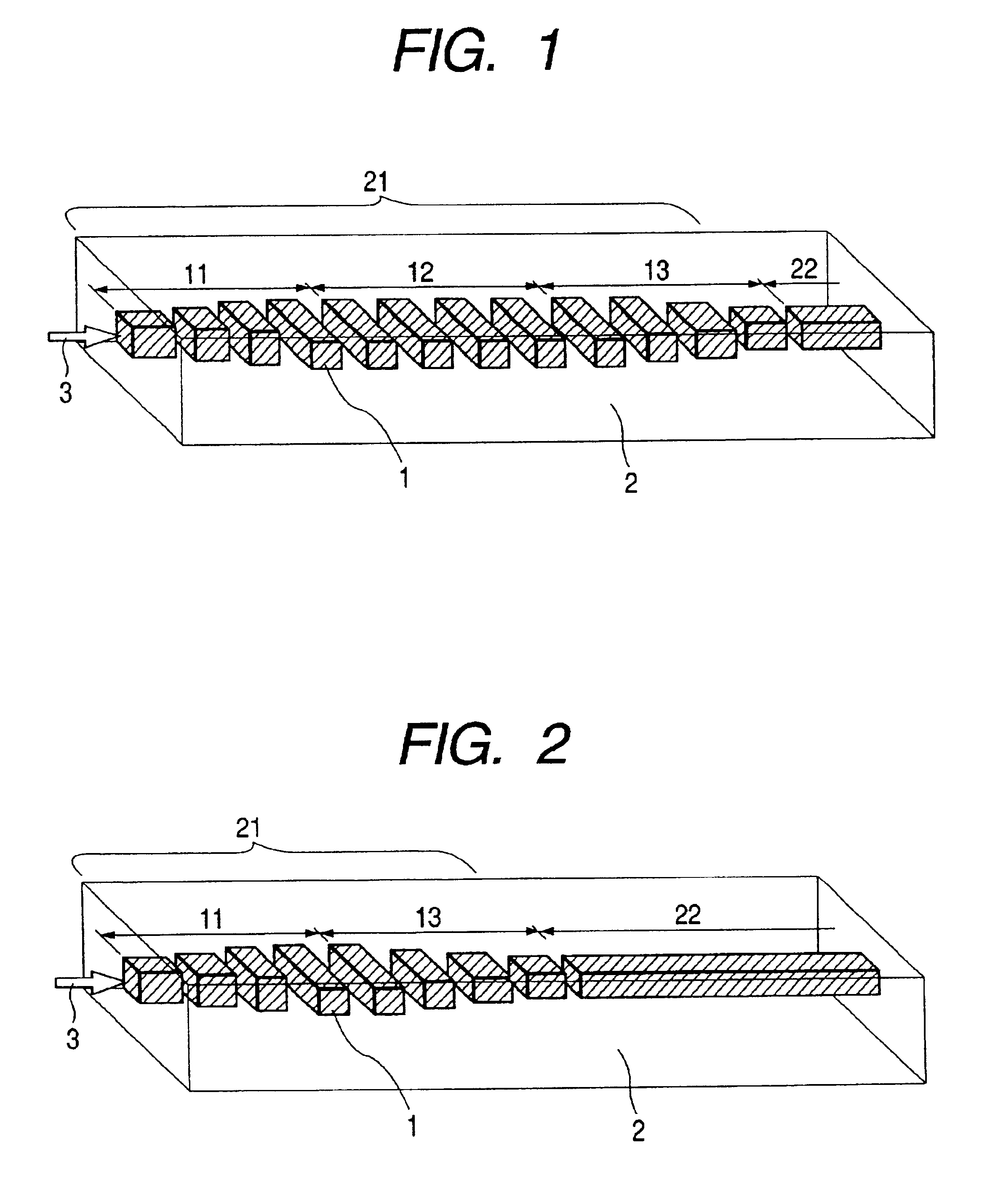
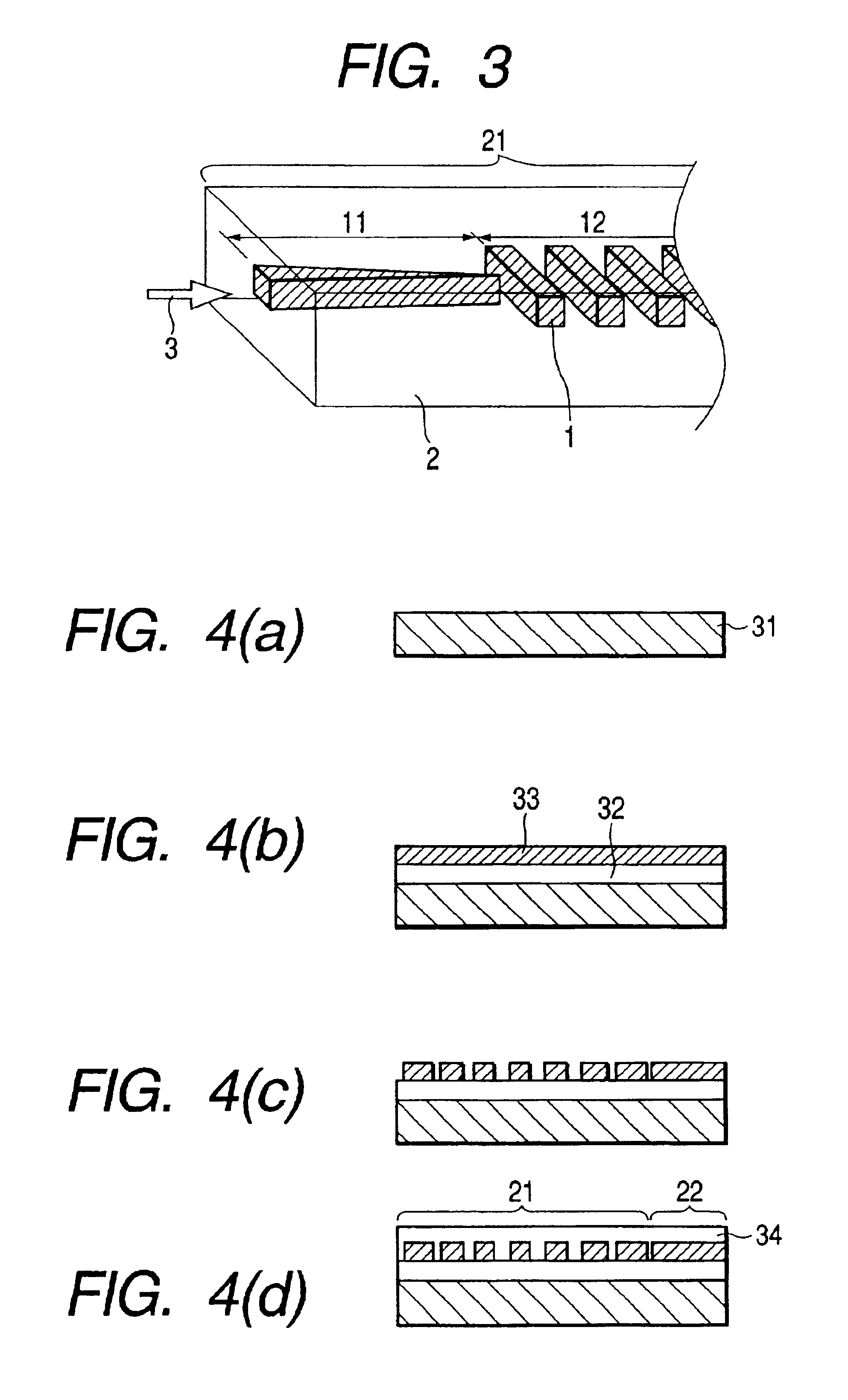
[0034]In FIG. 8, reference numeral 23 designates to an light emitting element such as a semiconductor laser, reference numeral 21 to a beam spot size converter waveguide for enlarging then shrinking the beam spot size, or for enlarging and maintaining then shrinking the beam spot size, reference numeral 22 to a waveguide that propagates the optical beam having the beam spot size converted by the beam spot size converter waveguide 21.

[0035]The beam spot size converter waveguide 21 in FIG. 8(a) includes a beam spot size enlarger waveguide 11 for enlarging the beam spot size to propagate the beam, and a beam spot size reducer waveguide 13 for shrinking the beam spot size to propagate the beam. The beam emitted from the light emitting element 23 such as a semicon...


PUM


Abstract

A beam spot size enlarger waveguide for enlarging the beam spot size is connected to a beam spot size reducer waveguide for shrinking the beam spot size, along with the direction of the propagation of light beam; or the beam spot size enlarger waveguide, a beam spot size maintainer waveguide for maintaining the beam spot size constantly, and the beam spot size reducer waveguide are connected in the direction of the propagation of light beam.

Description

BACKGROUND OF THE INVENTION[0001]1. Field of the Invention[0002]The present invention relates to an optical transmitter module used primarily in an optical transmission system or in an optical switching system (both referred to as an optical communication system) and more particularly to an optical connecting technology used for connecting a light emitting or receiving element with optical fibers in the optical transmission module, or a light emitting or receiving element with an optical circuit, as well as an optical circuit with optical fibers.[0003]2. Description of the Prior Art[0004]Construction of communication lines using optical fibers is projected not only among office buildings of a variety of industries but also among condominiums and residences, as the optical technology of communication develops. One of problems concerned is the cost of the optical transmission system, in particular the rate of lowering the cost of optical modules that reach to the subscribers. In the p...

Claims


Application Information

Patent Timeline
IPC IPC(8): G02B6/13G02B6/12G02B6/132G02B6/122G02B6/42H04B10/00H04B10/25
CPCG02B6/12004G02B6/122G02B6/1228G02B6/132G02B6/42
Inventor MATSUSHIMA, NAOKIKAWAMOTO, KAZUMI
Owner OCLARO JAPAN INC
Why Eureka
Try Eureka