Shears

a technology of shears and cutting tools, applied in the field of shears, can solve the problems that the solution employed in the above-mentioned u.s. patent no. 3,613,240 cannot be regarded as optimal in every way, and the tilting torque no longer increases

Active Publication Date: 2005-09-06
FISKARS CONSUMER
View PDF12 Cites 20 Cited by
  • Summary
  • Abstract
  • Description
  • Claims
  • Application Information

AI Technical Summary

Benefits of technology

[0005]Considering the above-mentioned lack of restriction of the force pressing the blades against each other in the shearing phase and pressing the blades away from each other in the opening phase of the shears, the solution employed in the above-mentioned U.S. Pat. No. 3,613,240 cannot be regarded as being optimal in every way. In order to improve this characteristic, the shears of the present invention are characteri

Problems solved by technology

Considering the above-mentioned lack of restriction of the force pressing the blades against each other in the shearing phase and pressing the blades away from each other in the opening phase of the shears, the solution employed in the above-mentioned U.S. Pat. No. 3,613,240 cannot be regarded as being optimal in every way.
When such tilting occurs, the double cone structure of

Method used


Image

  • Shears
  • Shears

Examples


Embodiment Construction

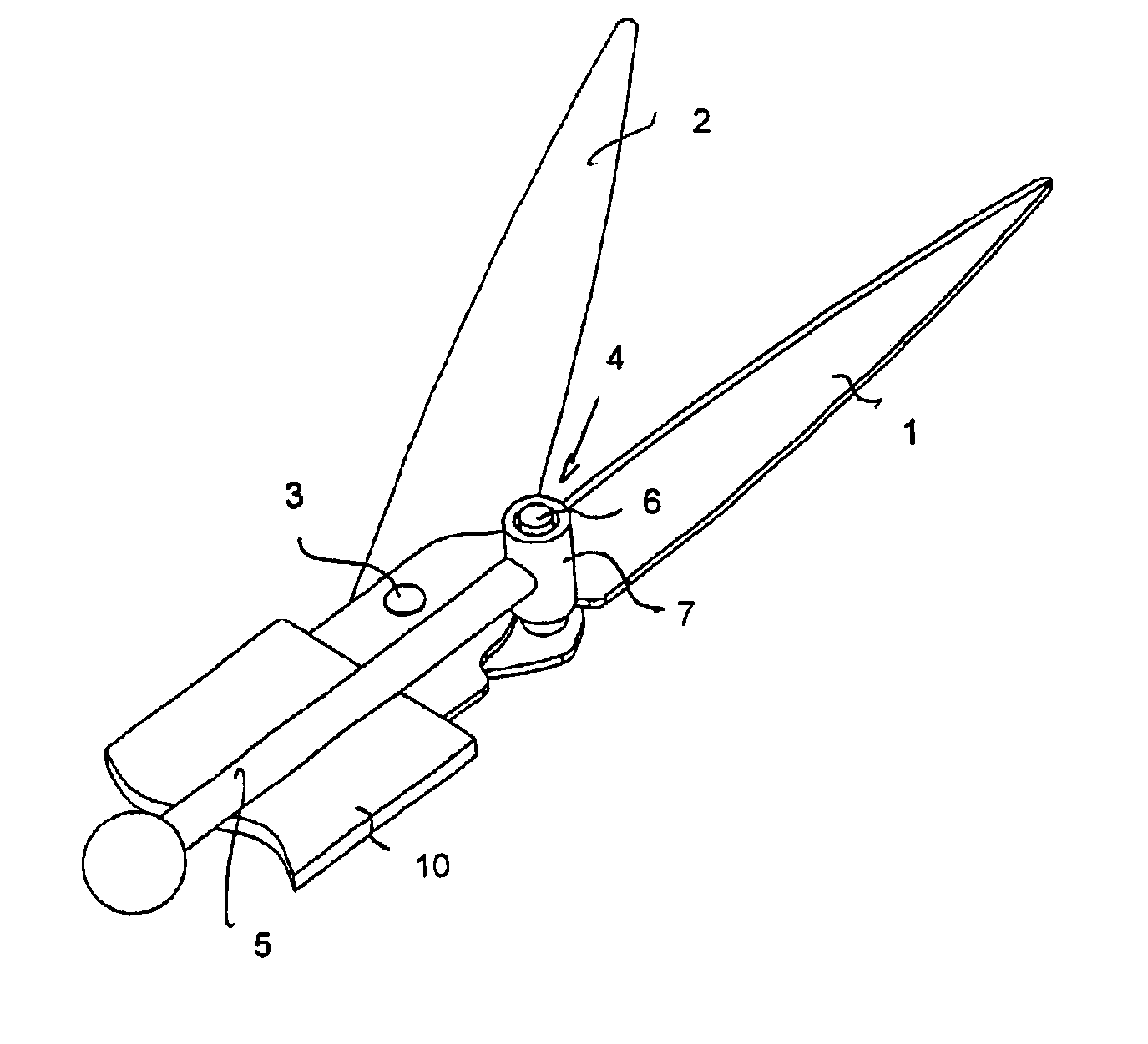
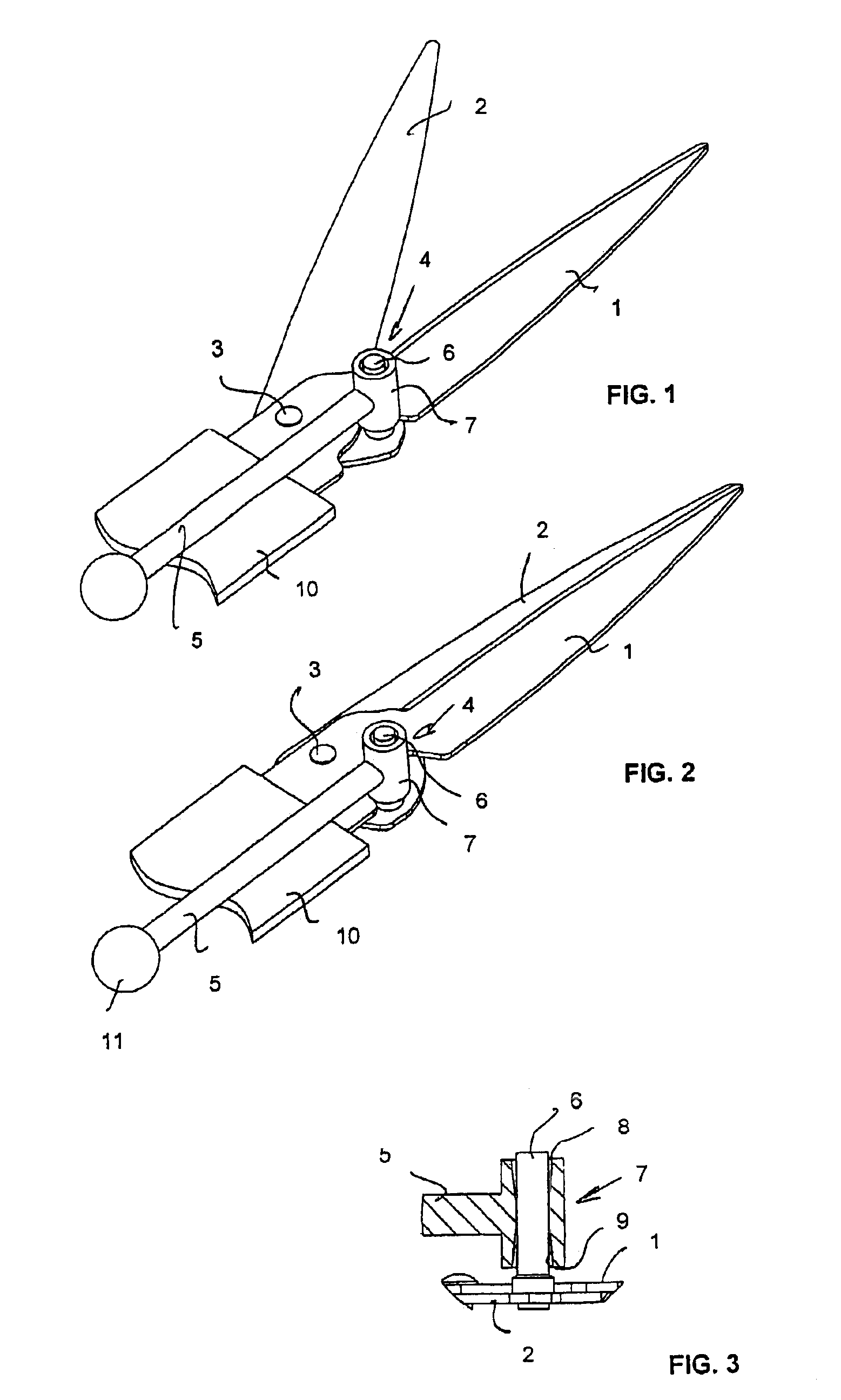
[0011]FIGS. 1 and 2 show shears according to an embodiment of the invention in an open and a closed position, respectively. Only parts of the shears relevant to the invention are shown. The main part of an operating mechanism has thus been omitted but alternative implementations thereof will be discussed below.

[0012]The shears disclosed in FIGS. 1 and 2 comprise a blade 1 which is stationary during a shearing movement of the shears, and a second blade 2 which moves during the shearing movement of the shears and which is connected to the blade 1 by a rivet-like joint 3. This articulated joint allows the blade 2 to turn with respect to the blade 1 around the joint 3. In the embodiment shown in FIGS. 1 and 2, the joint 3 is shown to be a stiff one, i.e. a relatively tight joint with little play. Such pivoting is common in conventional scissors for cutting paper, for instance.

[0013]If the shears of the invention are to be used for other purposes, e.g. as grass shears, a spring is conven...


PUM


Abstract

The invention relates to shears comprising a stationary blade (1) and a movable blade (2) which moves during the shearing movement of the shears. An operating mechanism (5) is arranged to affect a point of the pin (6) located at a distance from the movable blade (2). When the shears are being closed, a force is thus generated which also tries to pull the movable blade (2) towards and against the stationary blade (1) and to keep the blades (1, 2) in contact with each other. The operating mechanism (5) is arranged to affect the joint pin (6) through a sleeve-like part (7). The interior of the sleeve comprises two conical sections (8, 9), the narrowest point of the interior of the sleeve determining the point from which the sleeve-like part (7) affects the joint pin (6).

Description

FIELD OF THE INVENTION[0001]The present invention relates to shears comprising a first blade which is stationary during a shearing movement of the shears, and a second blade which moves during the shearing movement of the shears, a joint between the blades around which the movable blade is allowed to turn during the shearing movement between an open and a closed position with respect to the stationary blade, a second joint arranged at the side with respect to a line travelling via the joint between the blades and having a direction parallel with the longitudinal direction of the movable blade, the second joint comprising a pin projecting from the movable blade onto the side of the stationary blade, and an operating mechanism arranged to affect a point of the pin located at a distance from the movable blade and to direct to the second joint a force opening and closing the shears, the force also trying to pull the movable blade towards and against the stationary blade and to keep the ...

Claims


Application Information

Patent Timeline
IPC IPC(8): A01G3/00A01G3/06
CPCA01G3/065
Inventor LINDEN, OLAVIPALOHEIMO, MARKUS
Owner FISKARS CONSUMER
Why Eureka
Try Eureka