Power transfer unit

a power transfer unit and power transfer technology, applied in the direction of gearing details, machines/engines, transportation and packaging, etc., can solve the problems of affecting the efficiency of transmission and exhaust components, and reducing the life of gears and support bearings, so as to achieve the effect of reducing the weight of the power transfer uni

Inactive Publication Date: 2005-09-06
AUTOMOTIVE COMPONENTS HOLDINGS
View PDF9 Cites 5 Cited by
  • Summary
  • Abstract
  • Description
  • Claims
  • Application Information

AI Technical Summary

Benefits of technology

[0011]In overcoming the above mentioned and other drawbacks, the present invention provides a power transfer unit with a non-parallel gear set and a parallel gear set integrally packaged within a housing. The non-parallel gear set is coupled to the rear wheel drive line, and the parallel gear set is coupled between the non-parallel gear set and a transmission assembly. The housing includes an extension portion that mates the power transfer unit to the transmission assembly. The extension portion is formed having a structural web with one or more cavities. These cavities include inner cavities that define a portion of the interior volume of the housing and may also include outer cavities that open to the outside of the housing. The web between cavities provides structural rigidity for the power transfer unit, while the cavities minimize the weight of the power transfer unit.
[0013]In some configurations of the power transfer unit, cooling fins may be located within one or more of the outer cavities to enhance the heat rejection capabilities of the power transfer unit. Alternatively or additionally, cooling fins may be positioned over other parts of the exterior of the extension portion to increase the heat exchange performance of the power transfer unit.

Problems solved by technology

In addition, contaminants remaining in the power transfer unit from the production of the power transfer unit and additional contaminants generated by the wear of the internal components during the operation of the unit may reduce the life of the gears and support bearings.
Moreover, the gear sets, associated bearings, and the proximity of the engine, transmission and exhaust components may generate more heat than can be rejected from the main cavity or housing of the power transfer unit.

Method used


Image

  • Power transfer unit
  • Power transfer unit
  • Power transfer unit

Examples


Embodiment Construction

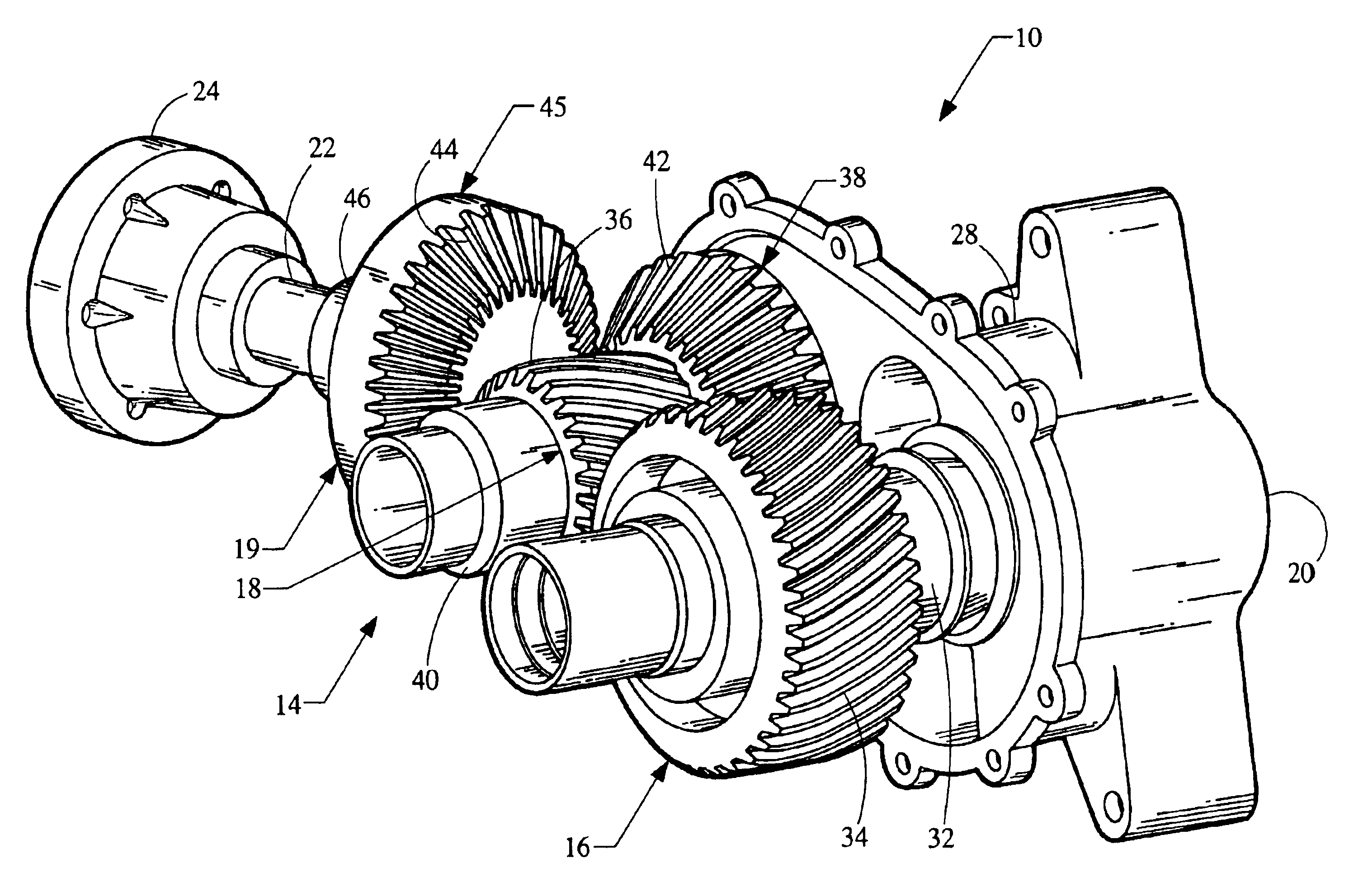
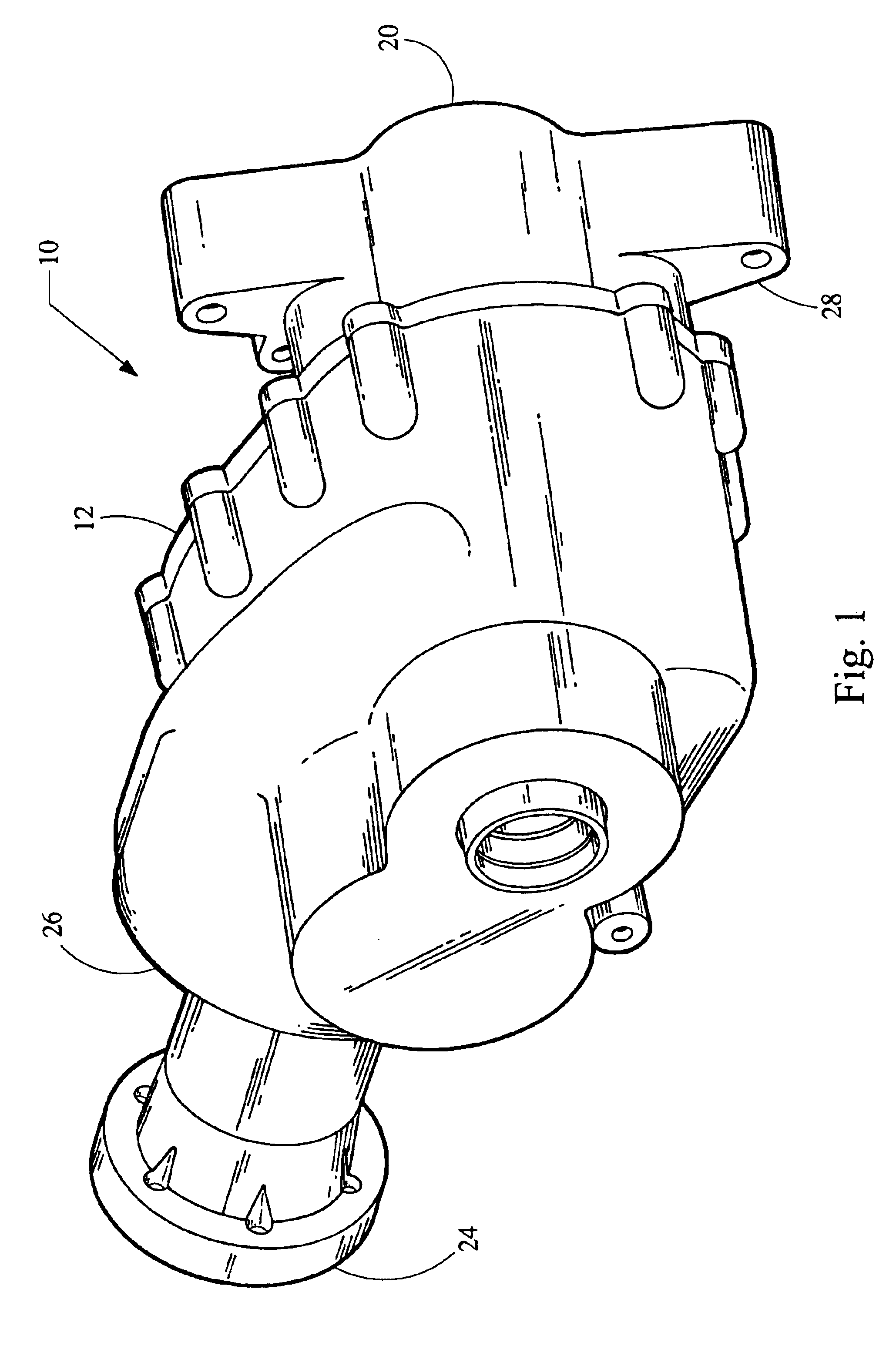
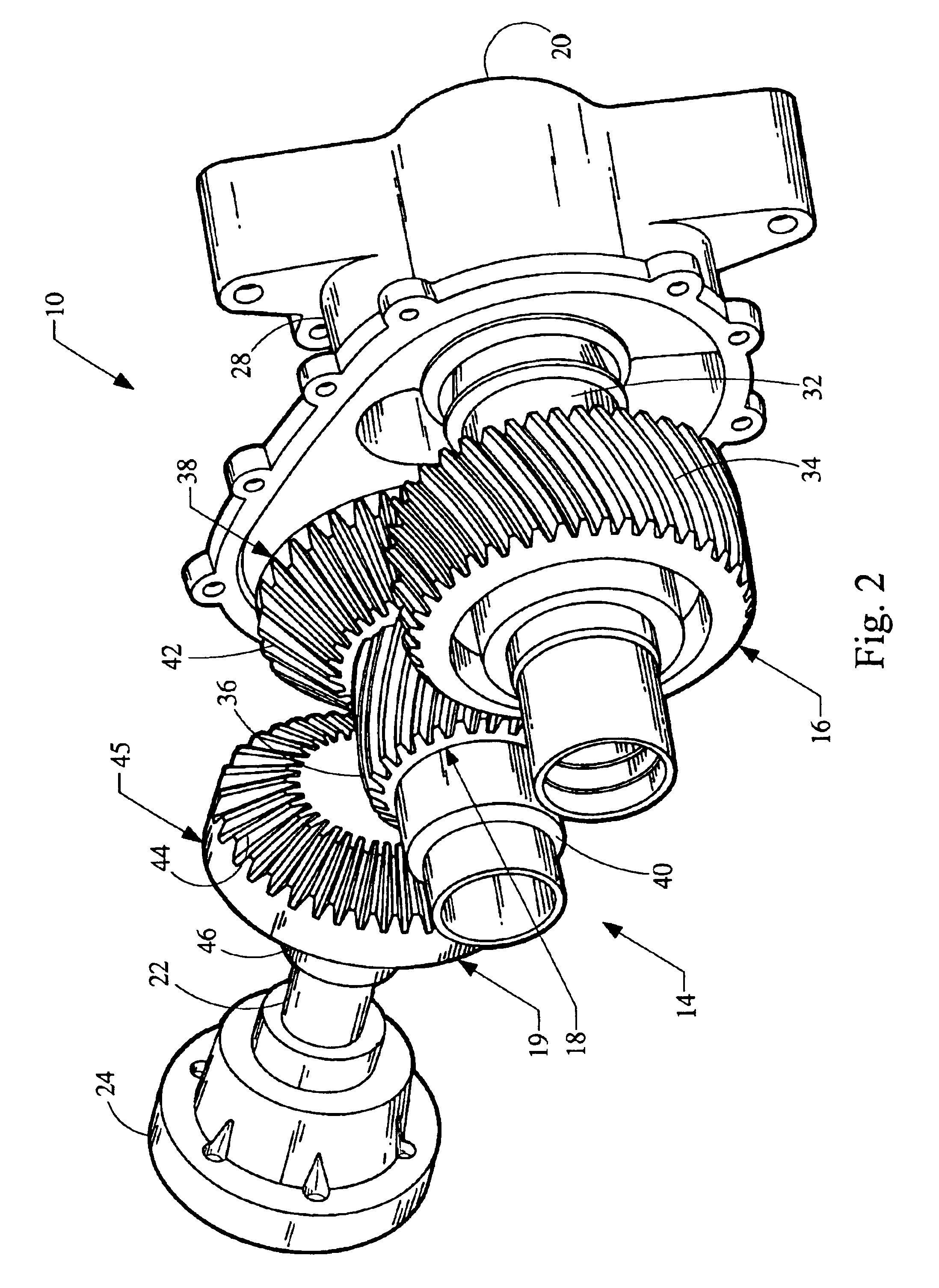
[0021]Referring now to the drawings, FIGS. 1 and 2 illustrate a power transfer unit 10 used for an all-wheel or four-wheel driveline, incorporating the principles of the present invention. The power transfer unit 10 includes a housing 12 in which the primary components of the unit 10 are integrally packaged. The components principally include a parallel gear set 14 of two or more gear wheels, such as a first helical gear 16 and a second helical gear 18, and a non-parallel gear set 19 of two bevel gears, such as the hypoid gears 38 and 44.

[0022]As used herein, the term “parallel gear set” is intended to refer to any mechanism (including, without limitation, mechanisms with gear wheels, mechanisms without gear wheels, gear trains, chain gears and belt systems), which transfer power from a first shaft to a second shaft, the first and second shafts defining axes that are generally parallel to one another.

[0023]As used here, the term “non-parallel gear set” is intended to refer to any me...


PUM


Abstract

A power transfer unit includes a non-parallel gear set and a parallel gear set integrally packaged within a housing. The housing includes an extension portion that connects the power transfer unit to a transmission assembly. The extension portion is formed having a structural web with one or more cavities. These cavities include inner cavities that define a portion of the interior volume of the housing and may also include outer cavities that open to the outer side of the housing. The web between cavities provides structural rigidity for the power transfer unit, while the cavities minimize the weight of the power transfer unit.

Description

BACKGROUND[0001]1. Technical Field[0002]The present invention relates generally to the power train of a motor vehicle. More particularly, the present invention relates to a power transfer unit for distributing power to the rear wheels of the vehicle.[0003]2. Background Information[0004]In the past, most automobiles in the United States utilized a rear wheel drive power delivery scheme. In adapting these rear wheel drive schemes into four wheel drive applications, a transfer case was, and often still is, positioned at the output of the transmission assembly. When engaged, the transfer case diverts a portion of the power coming from the transmission assembly from the rear wheels to the front wheels.[0005]Currently in the United States, a significant portion (if not a majority) of new automobiles are front wheel drive based vehicles. In a front wheel drive vehicle, both the engine and the transmission assembly are typically transversely oriented in the vehicle. By positioning the power...

Claims


Application Information

Patent Timeline
Patent Type & Authority Patents(United States)
IPC IPC(8): B60K17/344F16H57/02F16H57/027F16H57/03
CPCB60K17/344F16H57/027F16H57/0404Y10T74/2186F16H57/03
Inventor COOK, DENNISADLER, JONATHAN
Owner AUTOMOTIVE COMPONENTS HOLDINGS
Why Eureka
Try Eureka