Combustion resonator

a resonator and combustion technology, applied in the field of resonators, can solve the problem of inefficient reduction of engine noise at “non-optimum” engine speed

Inactive Publication Date: 2005-09-06
MAHLE TENNEX INDS
View PDF20 Cites 30 Cited by
  • Summary
  • Abstract
  • Description
  • Claims
  • Application Information

AI Technical Summary

Problems solved by technology

However, tuned resonators involve many design compromises which, invariably, make them inefficient in reducing engine noise at “non-optimum” engine speeds.

Method used


Image

  • Combustion resonator
  • Combustion resonator
  • Combustion resonator

Examples


Embodiment Construction

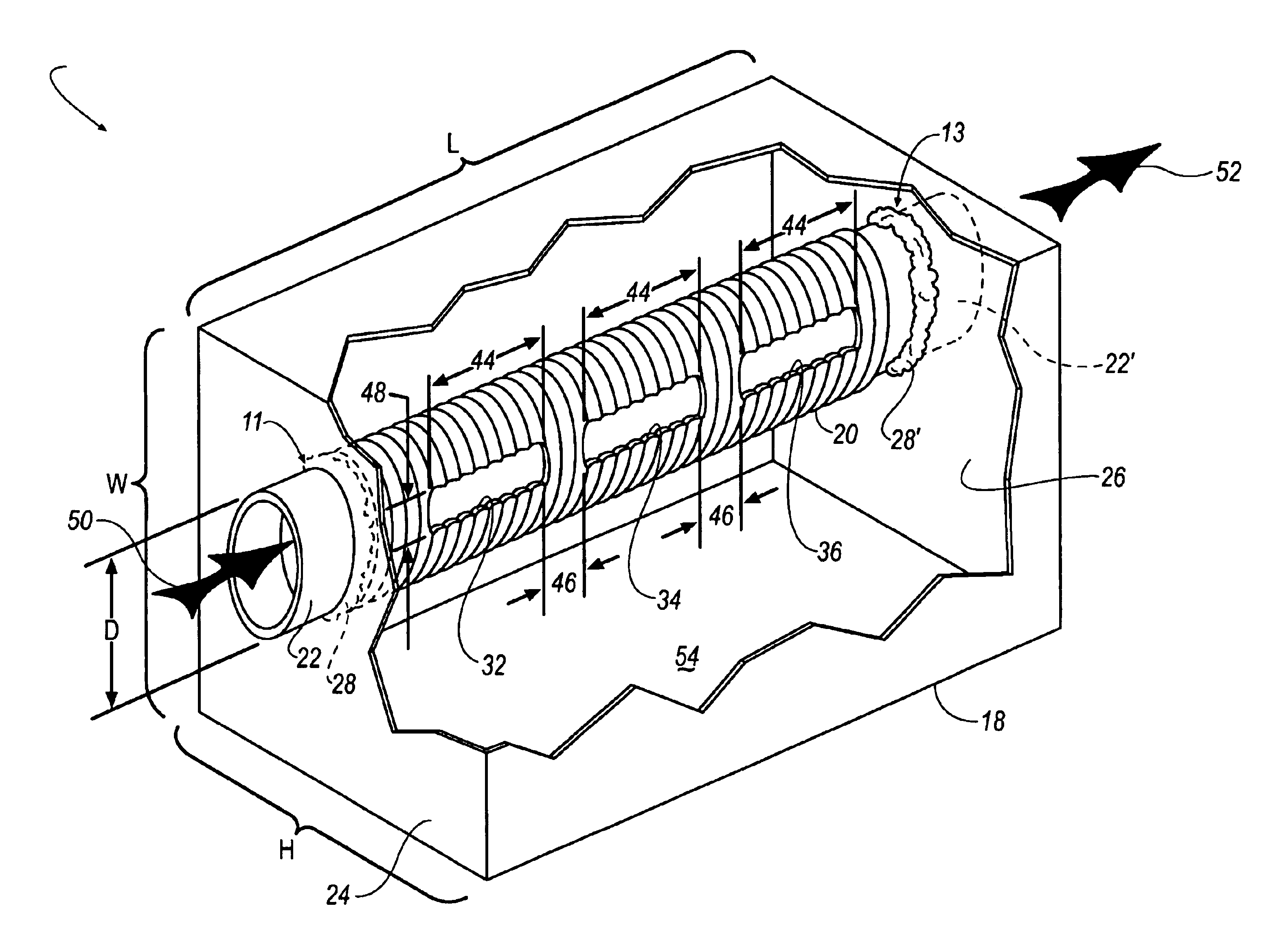
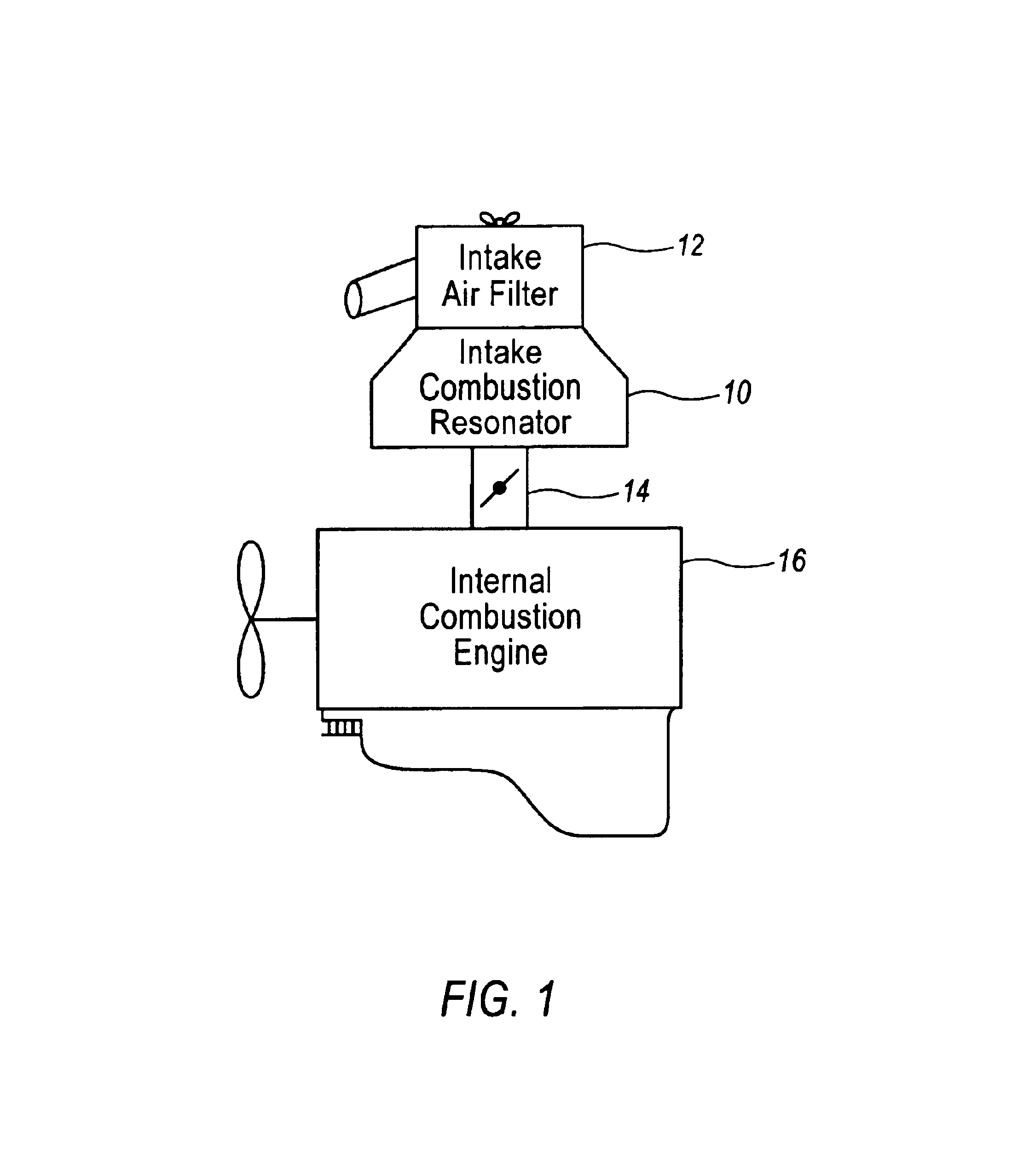
[0010]FIG. 1 is a general environmental view showing the intake combustion resonator 10 of the present invention in the environment in which it typically operates. Specifically, the intake combustion resonator 10 of the present invention is designed to reside between the intake air filter 12 and the throttle body 14 of internal combustion engine 16. It is to be understood that although FIG. 1 depicts the typical placement of intake combustion resonator 10 with respect to intake air filter 12, throttle body 14, and internal combustion engine 16, it is to be understood that many other arrangements of these components could be made without effecting the operation of the present invention. For example, combustion resonator 10 could reside between the air intake filter and the intake duct.

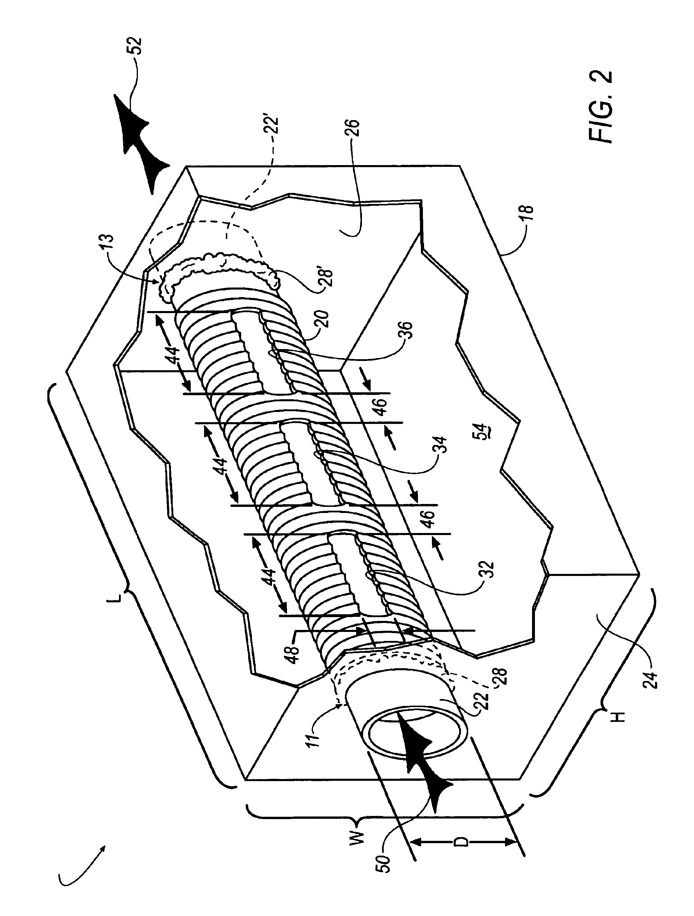
[0011]Now referring to FIGS. 1 and 2, intake combustion air resonator 10 is comprised of two primary components—enclosure 18, and porous tube element 20. End portions 22, 22′ of tube element 20 extend t...


PUM


Abstract

An intake combustion resonator including an enclosure which includes a resonator tube assembly passing through the enclosure. The resonator tube is formed from porous, undulated tube material and has openings formed in the tube walls. The openings serve as “tuned” passages through the porous tube walls. The resonator tube assembly is not centrally located within the enclosure but rather it is offset both in a height and a width orientation. The size, spacing, and orientation of the tube openings, porous, undulated sleeve material, the design of the enclosure, and the placement of the tube within the enclosure, all act in concert to give rise to the noise abatement properties of the present invention.

Description

TECHNICAL FIELD[0001]This invention generally relates to sound suppression devices and more particularly relates to resonators for attenuating sound produced by rotating machinery.BACKGROUND OF THE INVENTION[0002]It is generally desirable to minimize engine noise generated from internal combustion engines. Typically, this type of noise is reduced or minimized through the use of mufflers (for reducing combustion noise emitted from engine exhaust air) and the use of resonators (for attenuating the noise generated from the engine air intake system).[0003]One common approach to attenuating noise emitted from the intake portion of an engine, is to use resonators constructed from one or more interior chambers which are “tuned” in a way which cancels certain frequency ranges of intake noise. However, tuned resonators involve many design compromises which, invariably, make them inefficient in reducing engine noise at “non-optimum” engine speeds.[0004]A typical resonator includes an air rese...

Claims


Application Information

Patent Timeline
Patent Type & Authority Patents(United States)
IPC IPC(8): F01N1/02F01N1/08F02M35/12F02M35/14
CPCF01N1/02F02M35/14F02M35/1216F02M35/1255F02M35/1272F01N1/082F01N2210/04F01N2490/14
Inventor FUKUMOTO, ICHIRO
Owner MAHLE TENNEX INDS
Why Eureka
Try Eureka