Expandable spindle plug assembly for use with automatic tire inflation systems

a technology of automatic tire inflation and expansion spindle, which is applied in the direction of rod connection, manufacturing tools, transportation and packaging, etc., can solve the problems of oil leakage, damage to the o-ring seal and the interior wall of the spindle, and the adverse effect of the securement of the press plug assembly within the spindle and the seal created therewith

Inactive Publication Date: 2005-09-06
AIRGO IP
View PDF17 Cites 48 Cited by
  • Summary
  • Abstract
  • Description
  • Claims
  • Application Information

AI Technical Summary

Problems solved by technology

This can cause damage to the o-ring seal and the interior wall of the spindle during installation.
Any air leakage into the wheel lubrication compartment causes air pressure build up within the compartment which can damage the oil seals therein and create an oil leak.
If the wheel bearings lose their lubrication, they will seize up and can cause a fire.
Press plug removal for maintenance or cleaning of the axle presents another problem.
The interior of a trailer axle accumulates moisture from the air passing therethrough which causes rusting, creating debris in the form of rust particles within the axle that will clog the filter.
The removal of the press plug can not only destroy the press plug, it can damage the interior of the spindle to such an extent that it will not properly seal about a new press plug thus preventing a central tire inflation system being used on that axle in the future.
If the fasteners were unevenly torqued, the securement of the press plug assembly within the spindle and the seal created therewith could be adversely affected.
If the fasteners were not adequately torqued, neither a proper seal or securement would be obtained.
If the fasteners were over torqued the assembly could be damaged as the head portion required the use of an expansible material such as plastic.

Method used


Image

  • Expandable spindle plug assembly for use with automatic tire inflation systems
  • Expandable spindle plug assembly for use with automatic tire inflation systems
  • Expandable spindle plug assembly for use with automatic tire inflation systems

Examples


Embodiment Construction

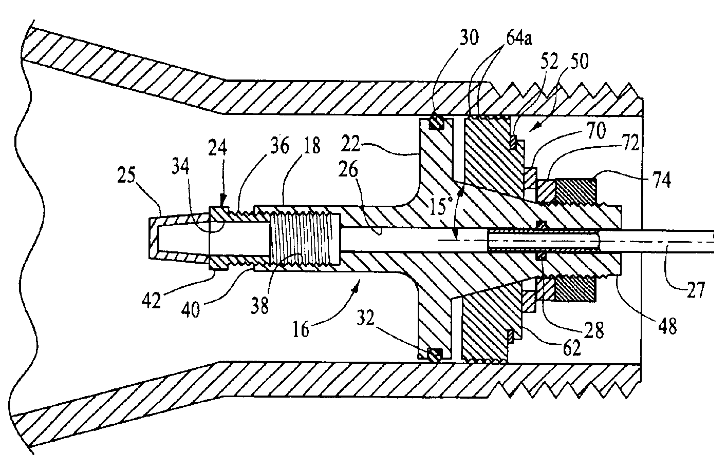
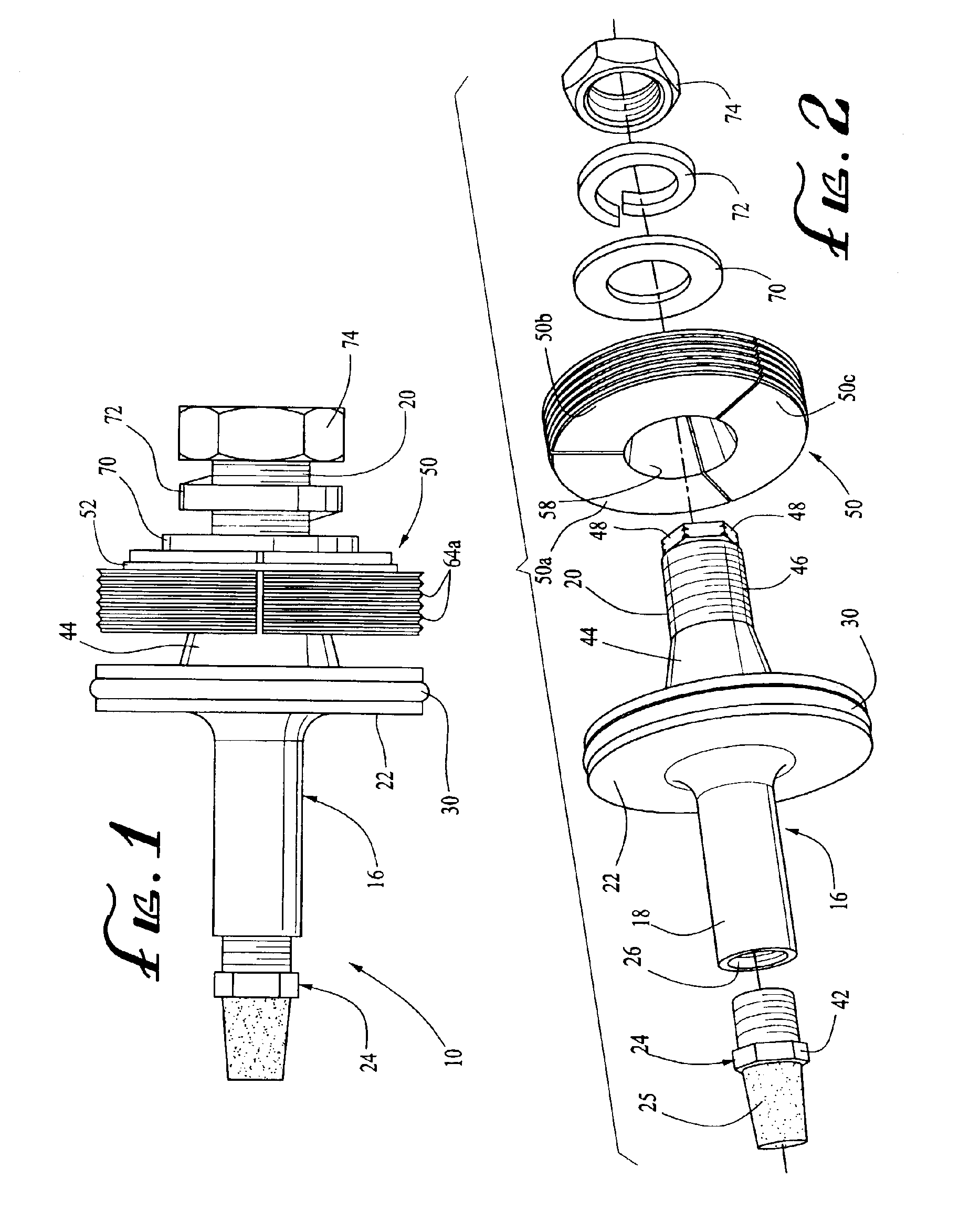
[0018]Referring now in detail to the drawings, the spindle plug assembly 10 of the present invention, while usable with automatic tire inflation systems on a wide variety of movable vehicles employing stationary axles with hollow spindles, is particularly adapted for use on tractor trailers. Accordingly, the assembly 10 will be described in conjunction with a stationary trailer axle 12. While identical spindle plug assemblies 10 are provided at the end of each axle on the trailer to communicate with a rotary union (not pictured) to maintain the inflation pressure of the tires carried thereby, reference will be made to only one such assembly 10 and the axle spindle 14 in which it is installed.

[0019]The spindle plug assembly 10 comprises an arbor 16 having an upstream portion 18, a downstream portion 20 and a circular flange 22 projecting radially between arbor portions 18 and 20. The arbor 16 and flange 22 are of single-piece construction, preferably forged from steel having a hardne...


PUM


Abstract

An assembly to be mounted in an axle spindle for communicating pressurized air from the axle to a rotary union in a tire inflation system. The assembly includes an arbor having an air flow channel extending therethrough, a flange intermediary of the arbor ends and an axially inclined portion proximate the flange. A sealing member is carried by the flange for forming an airtight seal with the axle spindle. A split ring locking assembly is disposed about the inclined portion of the arbor that is comprised of a plurality of segments held by an expansible retention spring. The segments move radially outwardly upon the locking assembly being moved along the inclined arbor portion and engage the axle spindle, securing the plug assembly within the spindle, A fastening member threadably engages the arbor for urging the locking assembly along the inclined arbor portion to effect securement of the plug assembly within the axle spindle.

Description

BACKGROUND OF THE INVENTION[0001]The present invention is directed to a spindle plug assembly for communicating pressurized air through an axle spindle to a rotary union assembly. Automatic tire inflation systems, also known as central tire inflation systems, are commonly used on tractor trailers and utilize compressed air as a source of pressurized air to fill a leaking tire while the trailer is in motion. The use of such inflation system is not limited to tractor trailers, however, but can be employed on any non-driven axle. References is made herein to tractor trailers as that is the most common use of such systems.[0002]In an automatic tire inflation system, air is directed from the control box to the leaking tire through one of the trailer's axles, which either carries an air line from the control box, or is sealed and functions as an air conduit. Pressurized air carried by the axles communicates with each pair of trailer tires mounted thereon through a plug assembly located at...

Claims


Application Information

Patent Timeline
Patent Type & Authority Patents(United States)
IPC IPC(8): B60C23/00
CPCB60C23/003Y10T403/7054Y10T403/7056B60C23/00336B60C23/00363
Inventor JARRETT, LARRY G.JONES, JOHNATHAN G.
Owner AIRGO IP
Why Eureka
Try Eureka