Apparatus and method for magnetic resonance measurements in an interior volume

a magnetic resonance and interior volume technology, applied in the field of magnetic resonance methods and devices, can solve the problems of inability to analyze only select portions of the enclosed volume and ignore signals from the rest, and achieve the effect of convenient measurement flexibility

Inactive Publication Date: 2005-09-06
HALLIBURTON ENERGY SERVICES INC
View PDF35 Cites 33 Cited by
  • Summary
  • Abstract
  • Description
  • Claims
  • Application Information

AI Technical Summary

Benefits of technology

[0006]Described herein is a magnet assembly for the generation of a magnetic field in an enclosed volume. More particularly, the magnet assembly used in accordance with the present invention generates a first, substantially homogeneous, magnetic field within an inner portion of an enclosed volume, and a second magnetic field throughout the remainder, i.e., the periphery of the volume, substantially different from the first magnetic field. Analyzed are only signals only within the inner portion of the enclosed volume, where the magnetic field is substantially homogeneous, whereas signals from the remaining portion of the enclosed volume are ignored. Both the dimensions of the inner portion and the parameters of the field in this portion can be adjusted, which provides desirable measurement flexibility.

Problems solved by technology

However, a problem with devices of this type is that because the magnetic field they generate is largely uniform and homogeneous over the entire enclosed volume, it is unfeasible to analyze only select portions of the enclosed volume and ignore signals from the rest.

Method used


Image

  • Apparatus and method for magnetic resonance measurements in an interior volume
  • Apparatus and method for magnetic resonance measurements in an interior volume
  • Apparatus and method for magnetic resonance measurements in an interior volume

Examples


Embodiment Construction

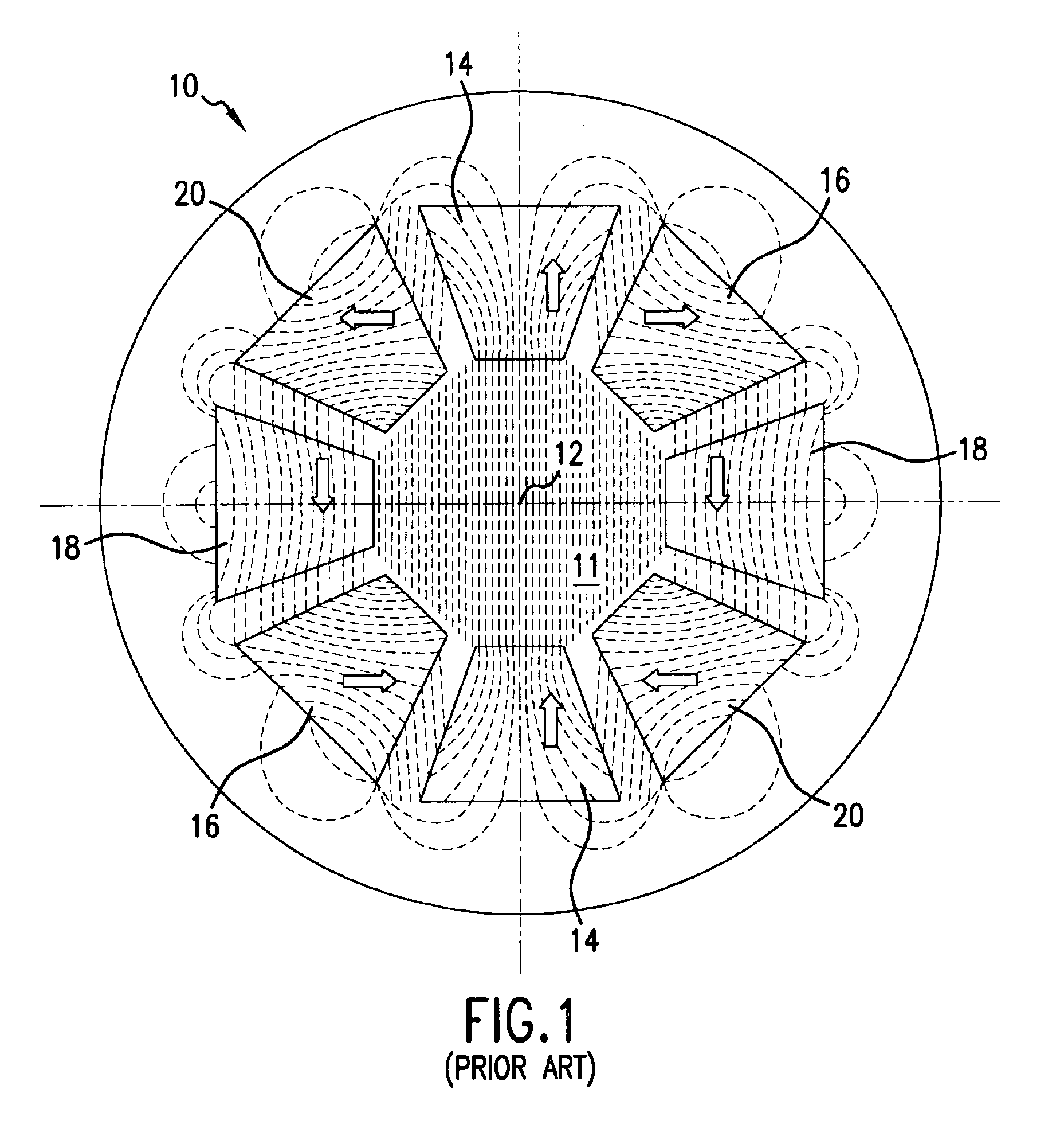
[0021]Reference is now made to FIG. 1, which illustrates a magnet assembly 10 and magnetic field configuration used in the prior art. Specifically, the structure shown in FIG. 1 is that described in Malcolm McGrieg and Alan G. Clegg, “Permanent Magnets in Theory and Practice,” Second Edition, John Wiley and Sons, 1987, and illustrated in FIG. 7.61 of the reference. The description of this structure in the McGrieg publication is incorporated herein by reference.

[0022]As shown in FIG. 1, eight permanent magnet blocks are arranged annularly to constitute an annular magnet assembly 10. The permanent magnet blocks are of trapezoidal column shape, hence the annular magnet assembly 10 forms a hollow trapezoidal tube or cylinder. In particular, magnet assembly 10 is constructed of four pairs of diagonally opposite magnets arranged symmetrically about the tubular volume 11 having a longitudinal axis 12 (pointing in a direction perpendicular to the drawing sheet) as follows: two magnets 14 ha...


PUM

PropertyMeasurementUnit
magnetic field intensitiesaaaaaaaaaa
magnetic resonance measurementsaaaaaaaaaa

Abstract

A magnet assembly and a magnetic field configuration are disclosed for the generation of a magnetic field in a defined volume, with the field being homogeneous over a pre-determined portion of the volume and not homogeneous over the rest. The disclosed magnetic assembly has a plurality of spaced-apart magnets arranged in pairs. The magnets of each pair are be positioned diametrically opposite each other with respect to an enclosed volume. In different embodiments magnets may all be arranged such that their magnetization directions are substantially aligned, or could alternatively be arranged to have magnetizations pointing in different directions. The angular spacing between the magnets is selected in the range of approximately 13°-17° and could be as large as the size of the magnets. The assembly generates a homogeneous magnetic field within an inner portion of the defined volume, and a second magnetic field, substantially different from the homogeneous magnetic field throughout the remainder, i.e., in the periphery of the defined volume.

Description

FIELD OF THE INVENTION[0001]The present invention relates generally to magnetic resonance methods and devices and in particular to generation of magnetic fields within a defined volume, and making corresponding measurements.BACKGROUND OF THE INVENTION[0002]Many applications of nuclear magnetic resonance (NMR) analysis of materials or magnetic resonance imaging (MRI) require a uniform, homogeneous magnetic field over a defined analysis volume. In practice, such analysis volume is usually generated within the interior of a device, and is shaped as a cylinder. Devices that provide such uniform homogeneous magnetic fields over a defined interior volume are also known. One such device, which is illustrated in block diagram form in FIG. 1, is described, for example, in Malcolm McGrieg and Alan G. Clegg, “Permanent Magnets in Theory and Practice”, Second Edition, John Wiley and Sons, 1987, which is incorporated by reference herein as background material.[0003]As shown in FIG. 1, the magnet...

Claims


Application Information

Patent Timeline
Patent Type & Authority Patents(United States)
IPC IPC(8): G01R33/38G01R33/383H01F7/02
CPCG01R33/383H01F7/0278
Inventor MILLER, MELVIN N.PRAMMER, MANFRED G.HUBER, MOTIKNIZHNIK, SERGEI
Owner HALLIBURTON ENERGY SERVICES INC
Why Eureka
Try Eureka