Method for forming thin film, apparatus for forming thin film, and method for monitoring thin film forming process

a technology of thin film and forming apparatus, which is applied in the direction of coating, chemical vapor deposition coating, plasma technique, etc., can solve the problems of low gas impermeability, low gas impermeability, and carbon dioxide transmission, and achieve stable gas impermeability, desirable flexibility, and the effect of not changing the surface quality

Inactive Publication Date: 2011-11-22
TOPPAN PRINTING CO LTD
View PDF29 Cites 0 Cited by
  • Summary
  • Abstract
  • Description
  • Claims
  • Application Information

AI Technical Summary

Benefits of technology

[0017]The present invention was conceived in view of the above circumstances, and an object thereof is to provide a thin film forming method and a thin film forming device, which can achieve a stable gas impermeability and a desirable flexibility in a thin film without variation in surface quality even if the thin film is formed onto a large number of substrates.
[0018]Another object thereof is to provide a thin film forming process monitoring method, and a thin film forming device, by which it is possible to know the structure of a generated plasma more accurately, and to know whether or not the produced thin film has a desirable surface quality during the process in which a mixture gas consisting of an organosilicon compound gas and an oxidizing gas is plasmatized, and a silicon oxide thin film is formed on a surface of the substrate.

Problems solved by technology

Although plastic containers have these advantages, plastic containers also have disadvantages in that a low molecular gas such as oxygen and carbon dioxide can be transmitted therethrough.
Such a disadvantage is called low gas impermeability because gas impermeability is low.
Occasionally, some of the contents in the container are affected undesirably by such gases.
However, it is difficult to recycle a material having a multi-layered structure which consists of at least two kinds of material.
Thus, there was a problem from an ecological point of view because a material having a multi-layer structure must be discarded after usage.
However, quite often, it was not possible to realize a desirable gas impermeability in a material having a multi-layer structure.
However, even if a thin film is formed by these methods, it is still difficult to control strictly flow ratio of a reactive gas and a monomer gas in the plasmatized process gas.
As a result, there has been a problem in that it was not possible to stably form a thin film having a sufficient gas impermeability, and in that, the gas impermeability varied even among the produced containers.
Furthermore, there has been another problem in that the gas impermeability of the thin film decreases because the produced thin film does not have sufficient flexibility, and finally, cracking occurs on the thin film when using the container.
It was not possible to know whether or not the thin film has a desirable surface quality during forming the thin film by the plasma CVD method.
However, the monitoring of the parameters, such as the degree of vacuum, applied power, and introduced gas flow amount, has not yet achieved the desirable surface quality of the produced thin film.
Firstly, although the hydrogen alpha rays have a relatively large intensity, the hydrogen beta rays have a small intensity, and the hydrogen beta ray vary greatly. Therefore, when the ratio between the intensity of the hydrogen beta rays and the intensity of the radiation of other atomic specimen (molecular specimen) is calculated, the calculated ratio varies greatly; thus, it is difficult to know the inner structure of the plasma accurately.
Therefore, there is a problem in that it is not possible to monitor the plasma accurately.
There is a problem because a specific complicated spectrometer is necessary for such a measurement, and such a spectrometer is expensive.

Method used


Image

  • Method for forming thin film, apparatus for forming thin film, and method for monitoring thin film forming process
  • Method for forming thin film, apparatus for forming thin film, and method for monitoring thin film forming process
  • Method for forming thin film, apparatus for forming thin film, and method for monitoring thin film forming process

Examples


first embodiment

[0046]Details of a first embodiment of the thin film forming method according to the present invention are explained with respect to the examples below, in which a thin film made of silicon oxide is formed on the inner surface of a plastic cylindrical container, which has a circular cross section with a closed end.

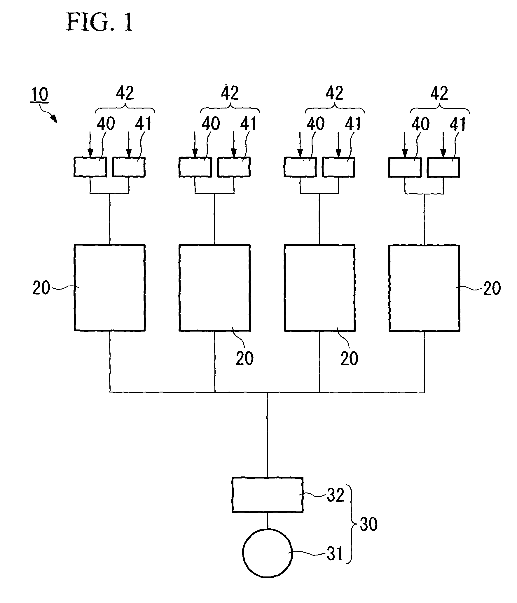
[0047]FIG. 1 shows an example of a thin film forming device 10 which is preferably used in the present embodiment of the thin film forming method. The thin film forming device 10 is provided with four sets of thin film forming chambers 20 which enables forming of thin films in the four sets of cylindrical containers 21 simultaneously by disposing the cylindrical containers 21 in predetermined positions in the thin film forming chambers 20.

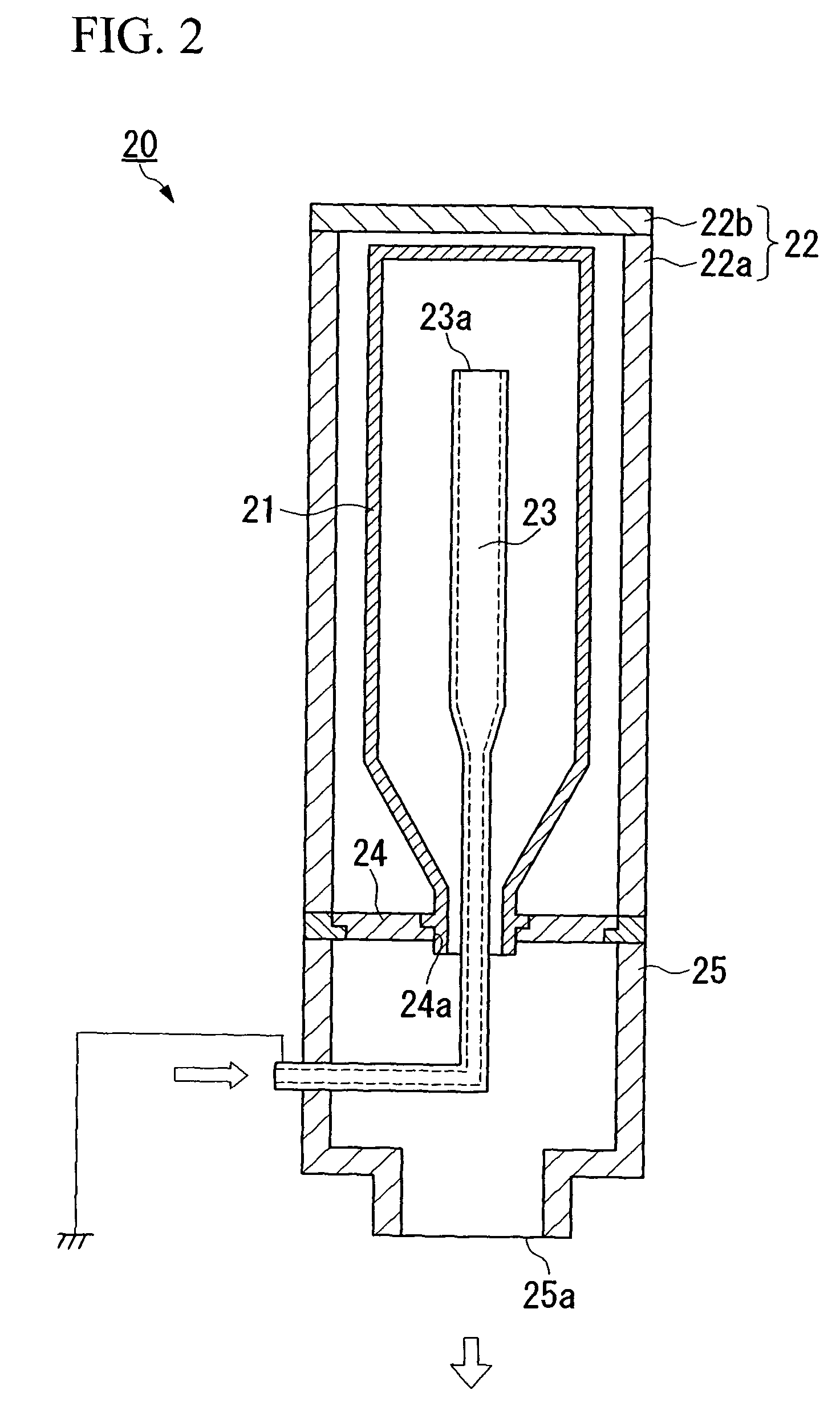
[0048]As shown in FIG. 2, each of the thin film forming chambers 20 is provided with a cylindrical high frequency electrode 22 having a circular cross section and a closed end, and a tubular ground electrode 23 of which the tip section is...

experimental example

[0087]Hereinafter, the present invention is explained specifically in detail with respect to Experimental Examples.

experimental example 1

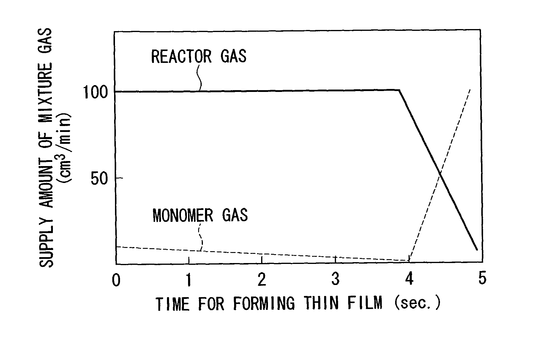
[0088]A cylindrical container 21, which is made of polyethyleneterephthalate and has a circular cross section and a 500 ml capacity, is disposed in a thin film forming chamber 20. The space in the thin film forming chamber 20 is evacuated (initial pressure for forming a thin film: 10 Pa). After that, the flow amount of hexamethyldisiloxane (monomer gas) and the flow amount of oxygen (reactive gas) are controlled by a mass-flow controller. The monomer gas and the reactive gas are supplied from the base end of the ground electrode 23 (gas introducing pipe). The initial supply flow amount of hexamethyldisiloxane is 10 ml / min. The initial supply flow amount of oxygen is 500 ml / min (that is, the initial supply flow amount ratio=0.02). Also, as shown in FIG. 3, the ground electrode 23, which has the gas generating port 23a at the tip section of the ground electrode 23, and consists of five approximately rectangular slits 23b with a 0.5 mm width, is prepared. Also, as shown in FIG. 7, the ...


PUM

PropertyMeasurementUnit
frequencyaaaaaaaaaa
widthaaaaaaaaaa
diameteraaaaaaaaaa

Abstract

A thin film forming method for plasmatizing a mixture gas, the mixture gas being made up of a monomer gas and an oxidizing reactive gas, and for forming a thin film on a surface of a substrate, the thin film being made of an oxide. The method includes forming a first thin film by plasmatizing the mixture gas while varying a supply flow amount ratio of the monomer gas with respect to the reactive gas and forming a final thin film by increasing the supply flow amount ratio of the monomer gas with respect to the reactive gas after the forming of the first film.

Description

[0001]This application claims the benefit under 35 U.S.C. §371, of International Application Number PCT / JP03 / 12334, filed Mar. 28, 2005, which claimed priority to the Japanese Patent Applications 2003-282653, filed Jul. 30, 2003 and 2002-287847, filed Sep. 30, 2002 in the Japanese Patent Office, the disclosures of which are thereby incorporated by reference.TECHNICAL FIELD[0002]The present invention relates to a thin film forming method and to a thin film forming device for forming a thin film, which is made of an oxide, on a substrate such as a plastic container. Also, the present invention relates to a thin film forming process monitoring method and to a thin film forming device for forming a silicon oxide thin film on a surface of a substrate by plasmatizing a mixture gas including an organosilicon compound gas and an oxidizing gas.BACKGROUND ART[0003]Plastic containers are used for packaging and containing purposes in various fields such as beverages, foods, toiletry goods, and ...

Claims


Application Information

Patent Timeline
Patent Type & Authority Patents(United States)
IPC IPC(8): H05H1/24C23C16/04C23C16/52
CPCC23C16/045C23C16/52
Inventor KAKEMURA, TOSHIAKIKASHIMA, HIROTOTSUJINO, MANABU
Owner TOPPAN PRINTING CO LTD
Why Eureka
Try Eureka