
Method and apparatus for modulating and demodulating digital data

a digital data and modulation method technology, applied in the field of methods and apparatus for modulating and demodulating digital data, can solve problems such as difficult implementation of dc control, and achieve the effect of high encoding ra

Active Publication Date: 2005-09-06
JVC KENWOOD CORP
View PDF9 Cites 43 Cited by
  • Summary
  • Abstract
  • Description
  • Claims
  • Application Information

AI Technical Summary

Benefits of technology

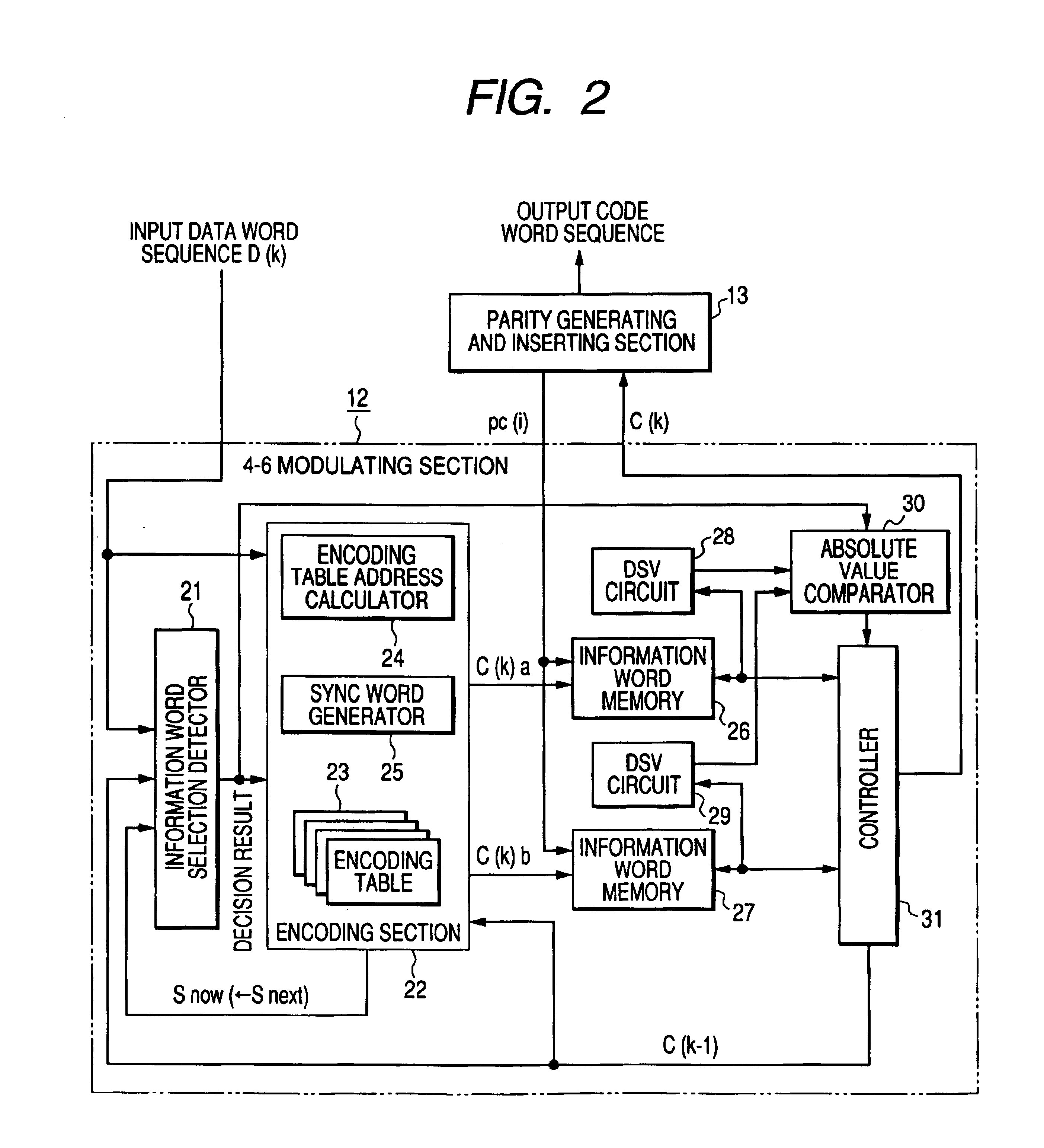
The invention provides an apparatus and method for modulating or encoding input digital data into (d, k) RLL DC-controlled LDPC-coded data at a high encoding rate. The apparatus includes a set of encoding tables, first means for modulating data words by referring to the encoding tables, and second means for generating a final information code word. The encoding tables contain information code words assigned to input data words, and the apparatus can handle a variety of input data. The method involves generating a final information code word and a first or second candidate information code word based on the input data, calculating a digital sum value for each code word, and selecting the smaller digital sum value as the final information code word. The invention also provides a modulating apparatus and method that can handle different types of input data and improve the efficiency of the modulation process.

Problems solved by technology

The implementation of the DC control is difficult when the inserted parity check bits are in specified polarity conditions.

Method used


Image

  • Method and apparatus for modulating and demodulating digital data
  • Method and apparatus for modulating and demodulating digital data
  • Method and apparatus for modulating and demodulating digital data

Examples


first embodiment

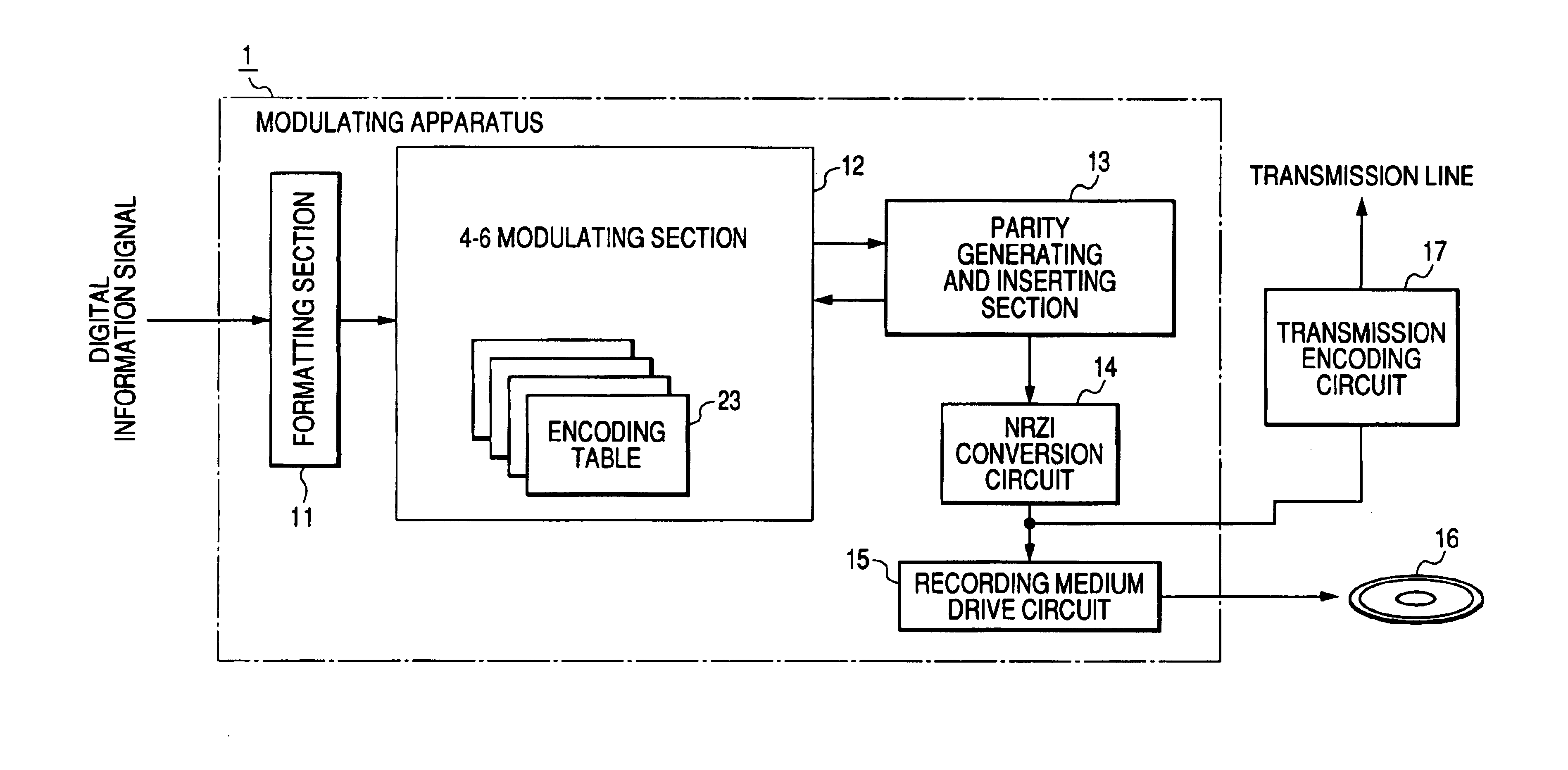
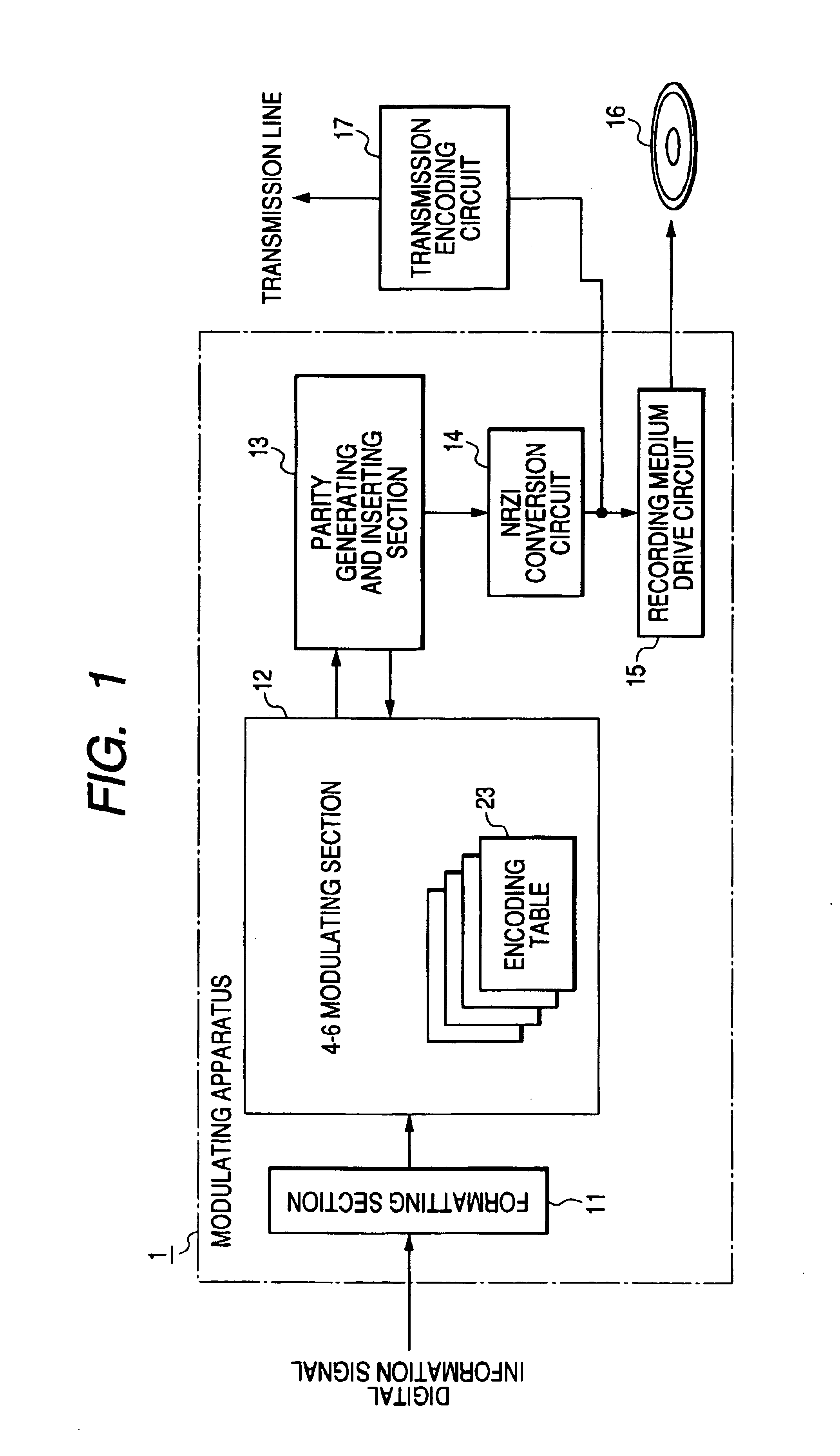
[0047]FIG. 1 shows an information modulating apparatus 1 according to a first embodiment of this invention. The information modulating apparatus 1 is designed as an information recording apparatus. The information modulating apparatus 1 includes a formatting section 11, a 4-6 modulating section 12, a parity generating and inserting section 13, an NRZI (non return to zero inverted) conversion circuit 14, and a recording-medium drive circuit 15 which are sequentially connected in that order. The recording-medium drive circuit 15 can access a recording medium 16 such as an optical disc. The information modulating apparatus 1 basically serves to modulate an input digital signal (an input digital information signal) representative of audio information, video information, or audio-visual information, and to record the modulation-resultant signal on the recording medium 16.

[0048]The NRZI conversion circuit 14 may be followed by a transmission encoding circuit 17 connected to a transmission...

second embodiment

[0188]FIG. 15 shows an information demodulating apparatus according to a second embodiment of this invention. The information demodulating apparatus receives an input bit stream generated by, for example, the information modulating apparatus 1 in FIG. 1. The input bit stream corresponds to, for example, the output signal of the NRZI conversion circuit 14 in FIG. 1. The information demodulating apparatus recovers original data words from the input bit stream.

[0189]The information demodulating apparatus in FIG. 15 includes an NRZI demodulator 50, a MAP decoder 51, a parity decoder 52, an LDPC decoder 53, a sync detector 54, a serial-to-parallel (S / P) converter 55, a word register 56, an address generator 57, a code-word decision-information detector 58, a state calculator 59, a decoding table 60, and a decoder 61.

[0190]The NRZI demodulator 50 receives the input bit stream. The NRZI demodulator 50 is connected with the MAP decoder 51. The MAP decoder 51 is connected with the parity dec...


PUM

PropertyMeasurementUnit
polarityaaaaaaaaaa
densityaaaaaaaaaa
lengthaaaaaaaaaa

Abstract

A succession of input data words is converted into a first succession of information code words including first candidate one and a second succession of information code words including second candidate one different from first candidate one. One is selected from the first succession of information code words and the second succession of information code words as a final succession of information code words in a manner such that the absolute value of a DSV relating to the final information-code-word succession will be smaller. Check bits are generated in response to the final information-code-word succession and a predetermined parity generation matrix of LDPC encoding. The check bits are changed to conversion code words. The final information-code-word succession and the conversion code words are combined into an output-code-word sequence which obeys (1, k) RLL, where “k” is a predetermined natural number in the range of 9 to 12.

Description

BACKGROUND OF THE INVENTION[0001]1. Field of the Invention[0002]This invention relates to a method and an apparatus for modulating or encoding input digital data into DSV-controlled (digital sum value controlled) digital data including information code words and LDPC (low density parity check) code words. In addition, this invention relates to a method and an apparatus for demodulating or decoding LDPC-code-added digital data into original digital data.[0003]2. Description of the Related Art[0004]In general, modulation systems are used for recording digital information signals on recording mediums such as optical discs or magnetic discs. Some modulation systems encode an input data bit stream into an output data bit stream obeying (1, k) RLL which means run length limiting rules such that 1 to k successive bits of “0” should be between bits of “1”. The output data bit stream is recorded on a recording medium. Especially, (1, 7) RLL is the most commonly employed.[0005]The direct-curr...

Claims


Application Information

Patent Timeline
Patent Type & Authority Patents(United States)
IPC IPC(8): H03M5/00H03M5/14G11B20/14H03M7/14H03M13/11H03M13/19H03M13/31H04L25/49
CPCH03M5/145H03M13/1102H03M13/31G11B20/1426
Inventor HAYAMI, ATSUSHI
Owner JVC KENWOOD CORP
Learn More