Overvoltage protection circuit

Inactive Publication Date: 2005-09-06
CIRRUS LOGIC INC
View PDF25 Cites 10 Cited by
  • Summary
  • Abstract
  • Description
  • Claims
  • Application Information

AI Technical Summary

Benefits of technology

[0009]According to the present invention, IC overvoltage protection techniques are provided which are not characterized by the foregoing disadvantages. According to a specific embodiment, an overvoltage protection circuit is provided in series with the input voltage VIN and the IC supply voltage VCC which regulates the current between the two. That is, the circuit functions to reduce the current flow when VCC is too high, and to increase the current flow when VCC is too low. According to a

Problems solved by technology

If any of the pins on an IC are subjected to a potential greater than this rated absolute maximum voltage, the device will be destroyed.
However there are situations where the overvoltage problem is unavoidable and some form of protection circuitry is needed in order to protect the IC.
The main problem with this solution is that the zener diode must pass large amounts of current and dissipate large amounts of heat.
As a result, this solution is only acceptable if the over voltage condition is for a short period (e.g., less than 1 or 2 seconds).
Otherwise the zener diode overheat

Method used


Image

  • Overvoltage protection circuit
  • Overvoltage protection circuit
  • Overvoltage protection circuit

Examples


Example

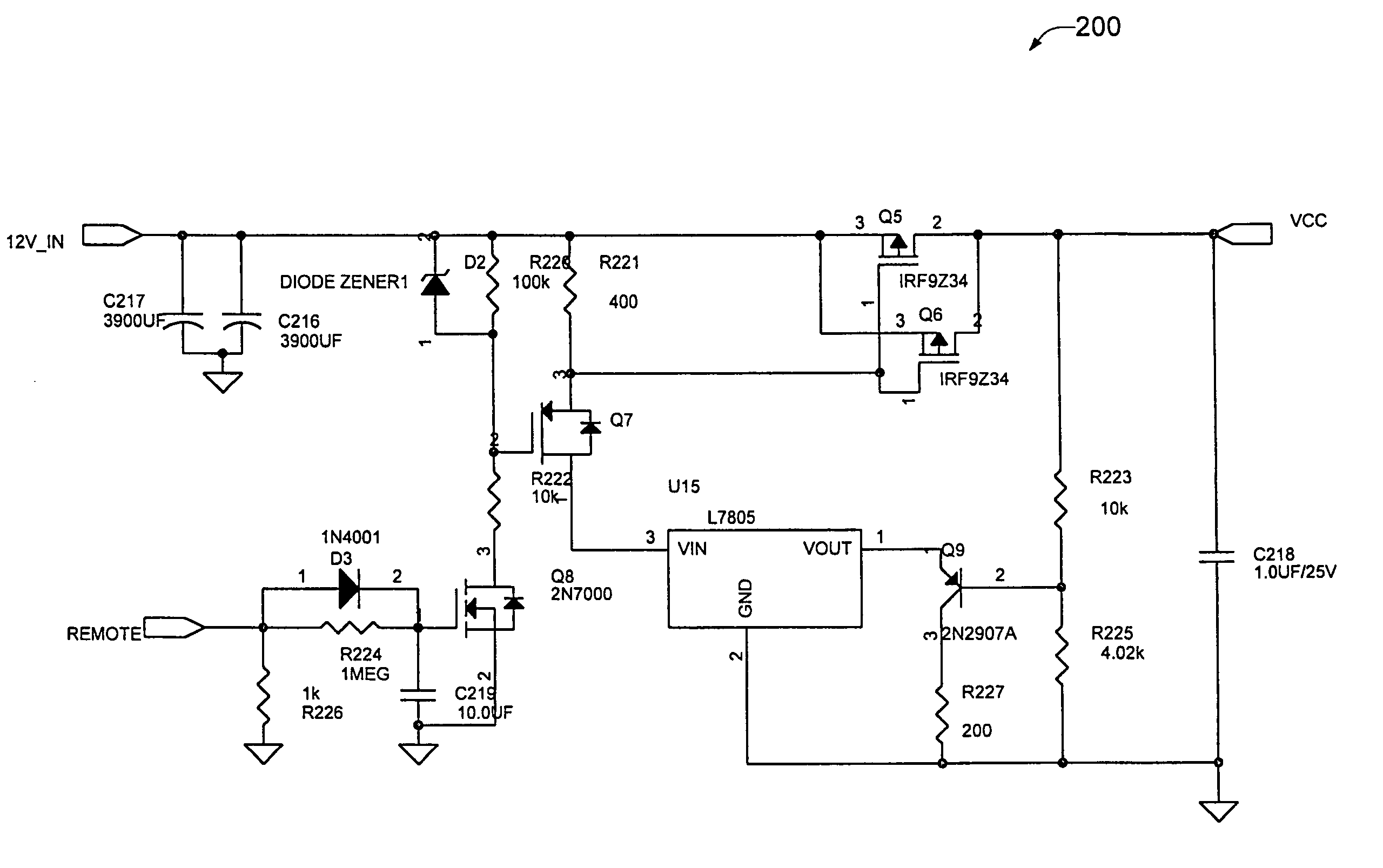
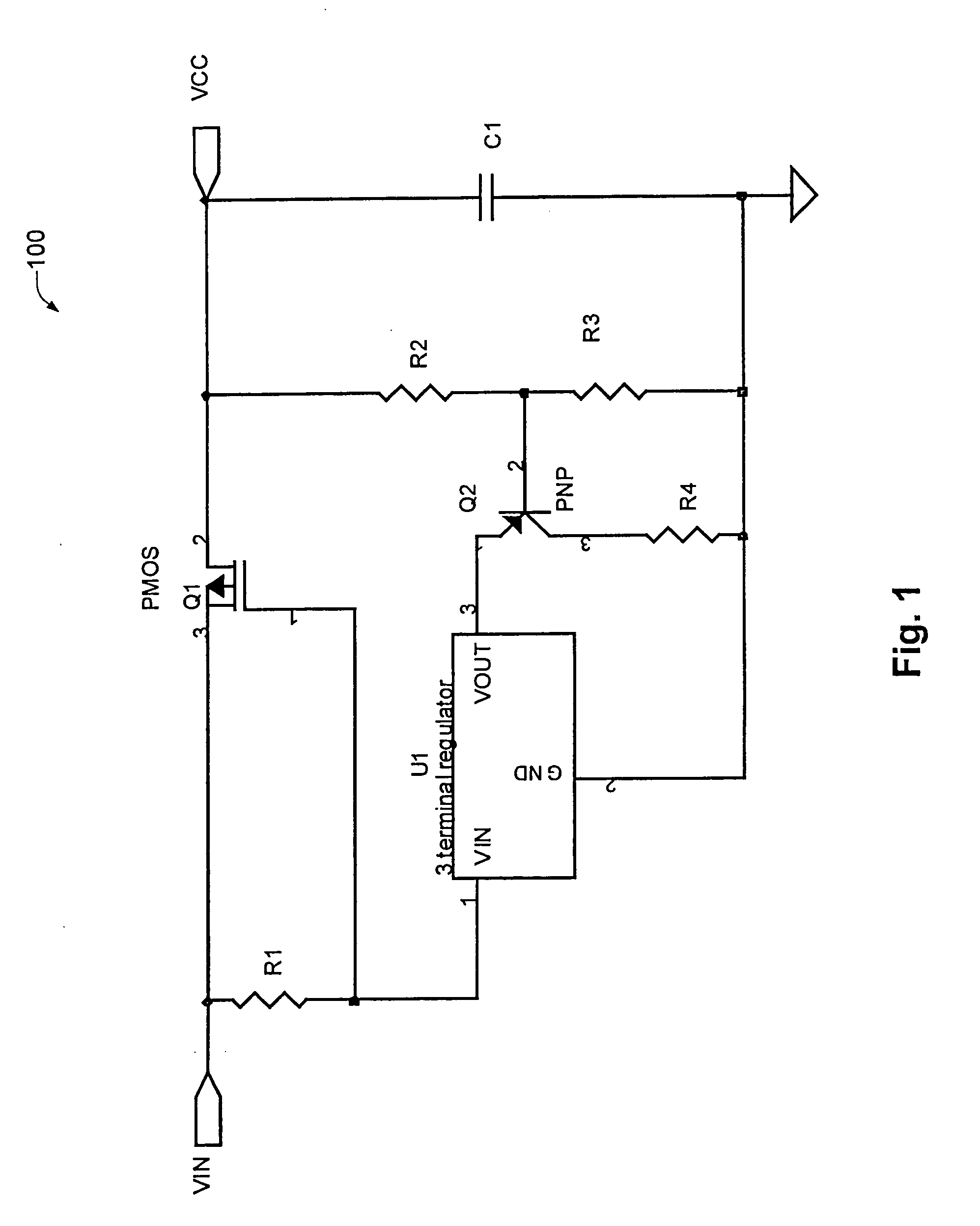
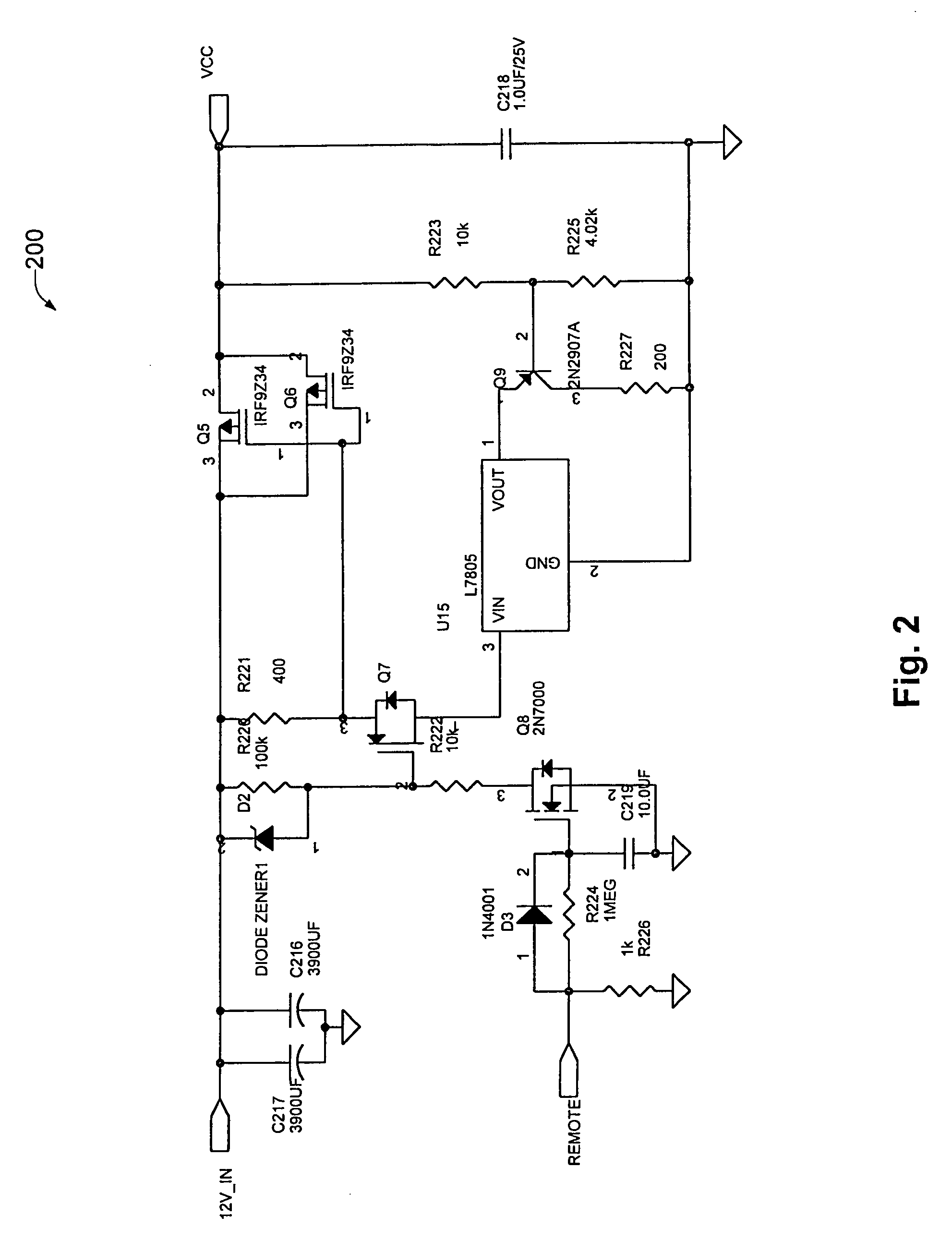
[0015]FIG. 1 is a simplified schematic of an overvoltage protection circuit 100 designed according to a specific embodiment of the present invention. As mentioned above, circuit 100 functions to reduce the current flow between VIN and VCC when VCC is too high and increase the current flow between VIN and VCC when VCC is too low. To accomplish this, circuit 100 uses a P-channel MOSFET (Q1) to pass current from VIN to VCC, a voltage divider (comprising resistors R2 and R3) to sense and scale VCC, an inverting voltage-controlled current source (VCCS) (including Q2 and U1) and a resistor (R1) to provide gate drive for Q1.

[0016]The VCCS includes R2, R3, Q2, and U1. According to a specific embodiment, U1 is a three terminal bucking DC voltage regulator. For purposes of explanation, we will assume U1 is a +5V regulator. However, it will be understood that the regulation value of U1 may be a wide variety of values without departing from the scope of the present invention. According to this ...


PUM


Abstract

An overvoltage protection circuit for interposing between an input voltage and a supply voltage is described. The overvoltage protection circuit includes switch circuitry connected to and passing current between an input voltage node and a supply voltage node, the input voltage node corresponding to the input voltage and the supply voltage node corresponding to the supply voltage. Switch control circuitry senses the supply voltage and regulates current flow through the switch circuitry in response thereto.

Description

RELATED APPLICATION DATA[0001]The present application claims priority from U.S. Provisional Patent Application No. 60 / 170,963 for OVERVOLTAGE PROTECTION CIRCUIT filed on Dec. 15, 1999, the entirety of which is incorporated herein by reference for all purposes.BACKGROUND OF THE INVENTION[0002]The present invention relates to overvoltage protection in integrated circuits. More specifically, the present invention provides techniques for protecting integrated circuits from overvoltage conditions of relatively long duration with no significant loss of supply voltage.[0003]Every integrated circuit (IC) is fabricated according to a process with a rated absolute maximum voltage. If any of the pins on an IC are subjected to a potential greater than this rated absolute maximum voltage, the device will be destroyed. Thus, the system designer must ensure that the IC is never subjected to a potential greater than the absolute maximum voltage in a given application. However there are situations w...

Claims


Application Information

Patent Timeline
IPC IPC(8): H02H9/04
CPCH02H9/04
Inventor KEMP, ALSONCHIU, MARSHALL
Owner CIRRUS LOGIC INC
Why Eureka
Try Eureka