
CPU cooling using a heat pipe assembly

Active Publication Date: 2005-09-06
SHUTTLE COMP GRP INC +1
View PDF32 Cites 37 Cited by
  • Summary
  • Abstract
  • Description
  • Claims
  • Application Information

AI Technical Summary

Benefits of technology

[0010]Accordingly, the cooling apparatus can be attached tightly to the CPU while the fan is attached to the computer's housing, so the vibration of the fan does not affect the performance of the CPU. In addition, while maintaining the ability to cool the CPU sufficiently, embodiments of the invention allow the computer to use a fewer number of fans. Having at least one fewer fan results in less noise, less energy consumed, lower cost, and less space used within the computer's main unit. Because no fan directly above the CPU is required, there are more options for the design of the computer. This is particularly important for computer main units in which small size is desirable.

Problems solved by technology

However, since the CPU is typically contained within a computer housing, the heat generated by the CPU and dispersed by the fan does not necessarily escape the computer's housing.
Therefore, the use of this additional fan increases the noise inside the computer.
The extra noise is unpleasant for the user, especially when the computer is used for multimedia applications.
Also, this additional fan takes up space inside the computer main unit.
In small profile computer systems, space is at a premium, so the additional fan is undesirable.
Lastly, the fan directly over the CPU may cause vibrations in the CPU, which may affect its performance.

Method used


Image

  • CPU cooling using a heat pipe assembly
  • CPU cooling using a heat pipe assembly
  • CPU cooling using a heat pipe assembly

Examples


Embodiment Construction

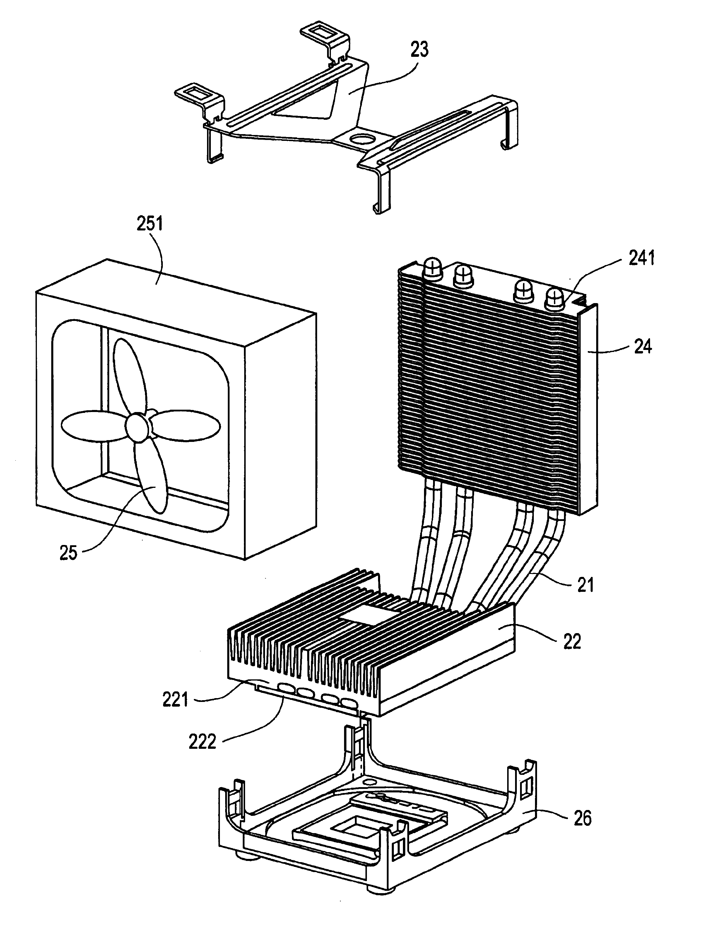
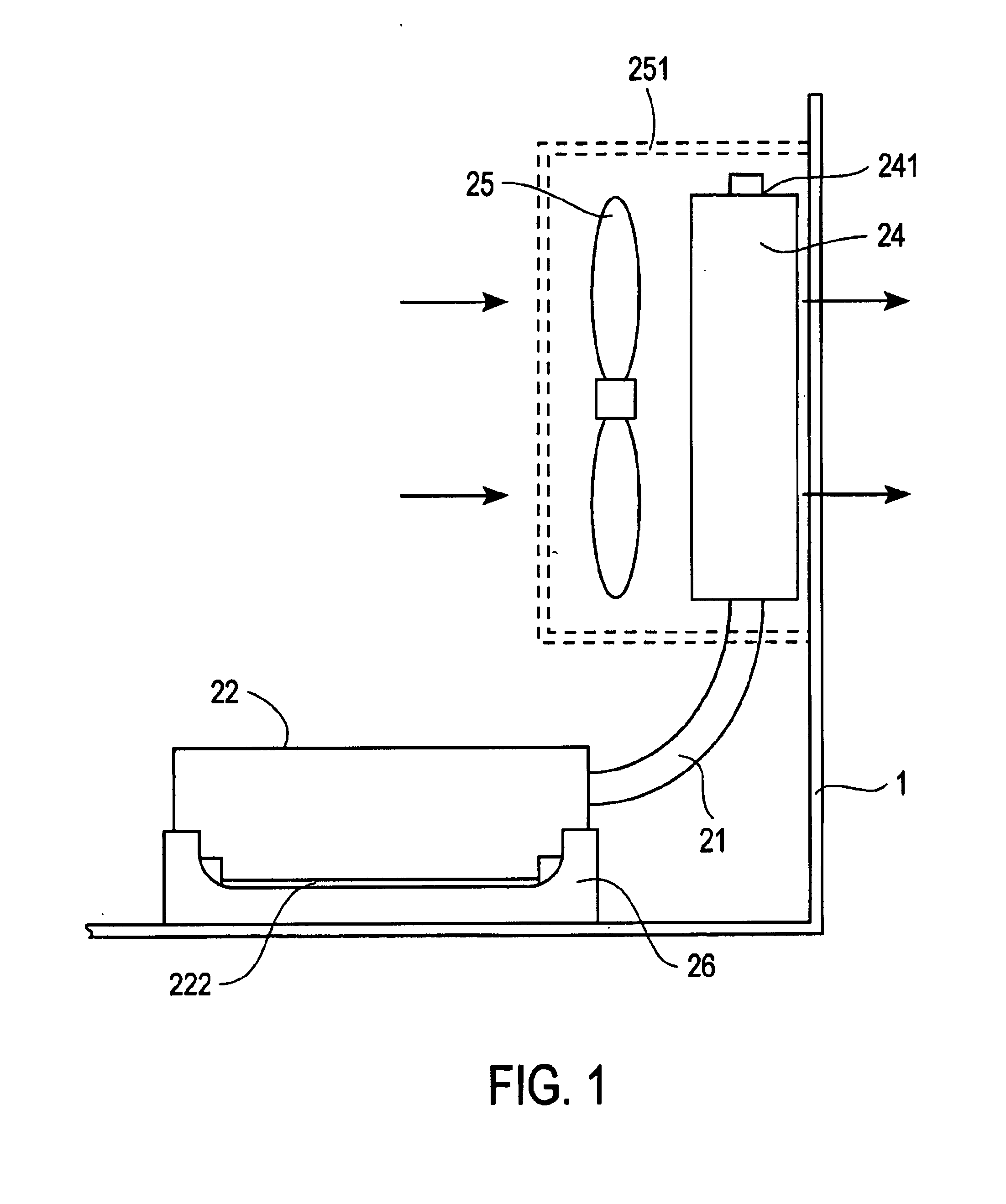
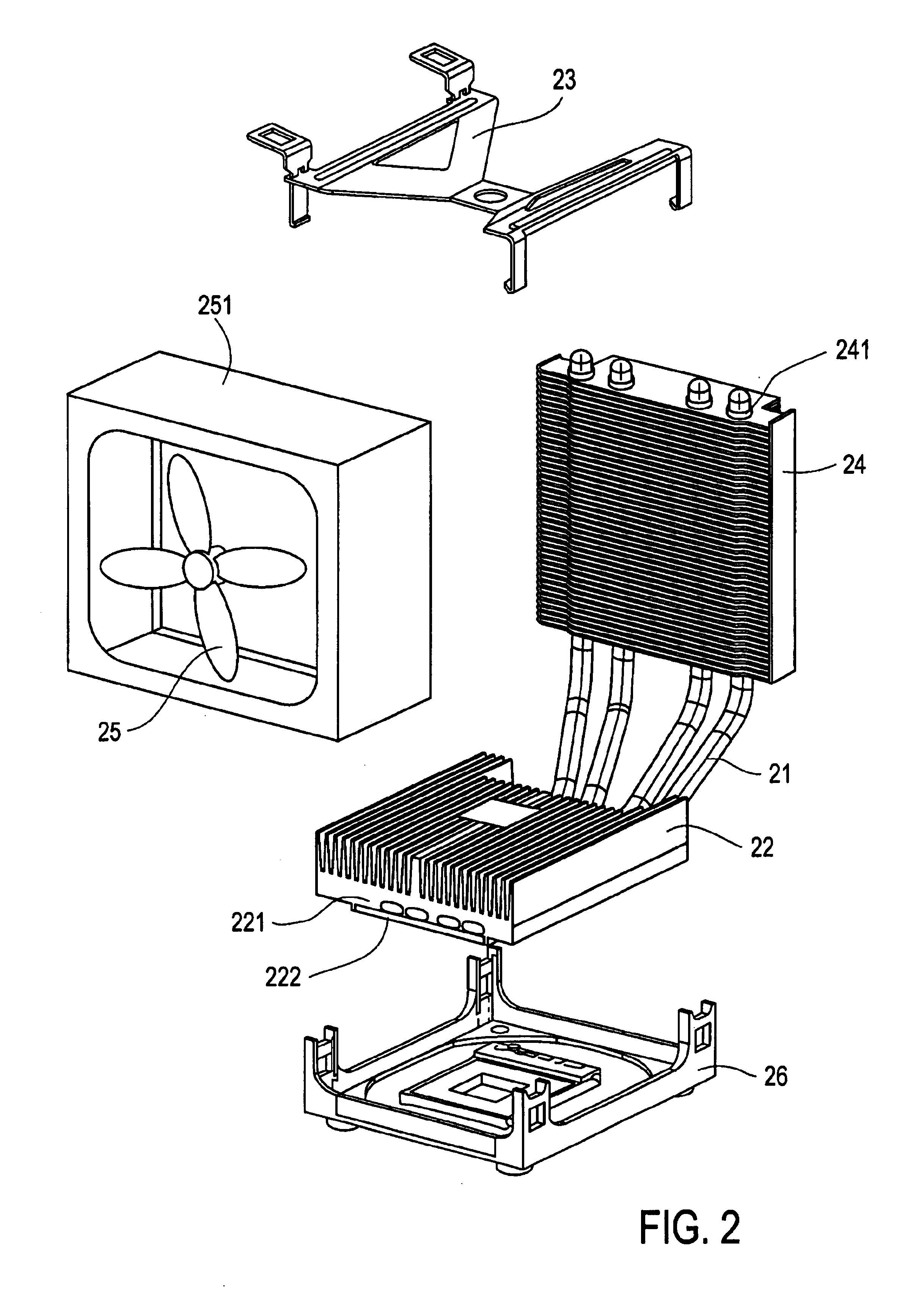
[0016]FIGS. 1(a), (b), and (c) respectively show a top view, a side view, and a rear view of a cooling apparatus in accordance with an embodiment of the present invention, and FIG. 2 shows an assembly diagram of the cooling apparatus in accordance with an embodiment of the present invention. The cooling apparatus comprises one or more heat pipes 21, a fin 22, a fastener 23, a plurality of heat sinks 24, and a fan 25. In one embodiment, the cooling apparatus includes four or more heat pipes elements for cooling a CPU.

[0017]A fin 22 is placed over a CPU and then fastened to a CPU socket using a fastener 23. The fin 22 has a bottom 221, wherein the bottom 221 of the fin 22 is hollow. A heat pipe 21 passes through the hollow bottom221 of the fin 22 and bonds to it to make thermal contact therewith. A sheet 222 covers the hollow bottom 221. In one embodiment, the heat pipe 21 has a metal weave interior for effectively conducting heat energy. The heat pipe 21 may also have water or anothe...


PUM


Abstract

A CPU cooling apparatus comprises a fin, a heat sink, and a heat pipe thermally coupling the fin and the heat sink. When installed in a personal computer, the fin thermally couples with a CPU to receive heat generated by the CPU. The heat pipe conducts the heat to a heat sink, which is cooled by an exhaust fan that directs a flow of air outside the computer.

Description

CROSS REFERENCE TO RELATED APPLICATIONS[0001]This application claims the right of priority based on Taiwan application serial no. 091206737, filed on May 13, 2002, which is herein incorporated in its entirety by reference.BACKGROUND[0002]1. Field of the Invention[0003]The present invention relates generally to cooling a central processing unit (CPU) of a computer.[0004]2. Background of the Invention[0005]Because of its critical role, the CPU of a computer generates a significant amount of heat but must operate at a sufficiently low temperature to avoid degradation in its performance. In the typical personal computer, the CPU is cooled by placing a finned heat sink directly above and in thermal contact with the CPU. A fan is positioned above the heat sink. The fan generates a flow of air immediately above the heat sink, removing the heat generated by the CPU away from an area near the CPU and heat sink, in turn, cooling the surrounding air. Because heat transfer from an object to its...

Claims


Application Information

Patent Timeline
IPC IPC(8): H01L23/467H01L23/34H01L23/427
CPCH01L23/427H01L23/467H01L2924/0002H01L2924/00
Inventor SHIH-TSUNG, CHEN
Owner SHUTTLE COMP GRP INC
Learn More