Method and apparatus using intensity gradients for visual identification of 2D matrix symbols

a technology of intensity gradients and matrix symbols, applied in the field of industrial vision systems, can solve the problems of increasing the delay and potential human errors of recalibrating for each run, requiring operator intervention, and reducing the reliability of so as to increase reliability and throughput, accurate locating the encoded symbol matrix

Inactive Publication Date: 2005-09-06
COGNEX CORP
View PDF47 Cites 38 Cited by
  • Summary
  • Abstract
  • Description
  • Claims
  • Application Information

AI Technical Summary

Benefits of technology

[0014]The present invention provides a new and useful system whereby visual information regarding intensity and gradient are used in a multi-step process for accurately locating an encoded symbol matrix. The system combines gradient information intelligently with intensity inf

Problems solved by technology

A large variety of marking procedures can be used, and recalibration for each run adds delay and potential human errors.
A failure to identify these attributes prior to decoding can cause an expensive rejection that may require operator intervention.
Stopping production

Method used


Image

  • Method and apparatus using intensity gradients for visual identification of 2D matrix symbols
  • Method and apparatus using intensity gradients for visual identification of 2D matrix symbols
  • Method and apparatus using intensity gradients for visual identification of 2D matrix symbols

Examples


Embodiment Construction

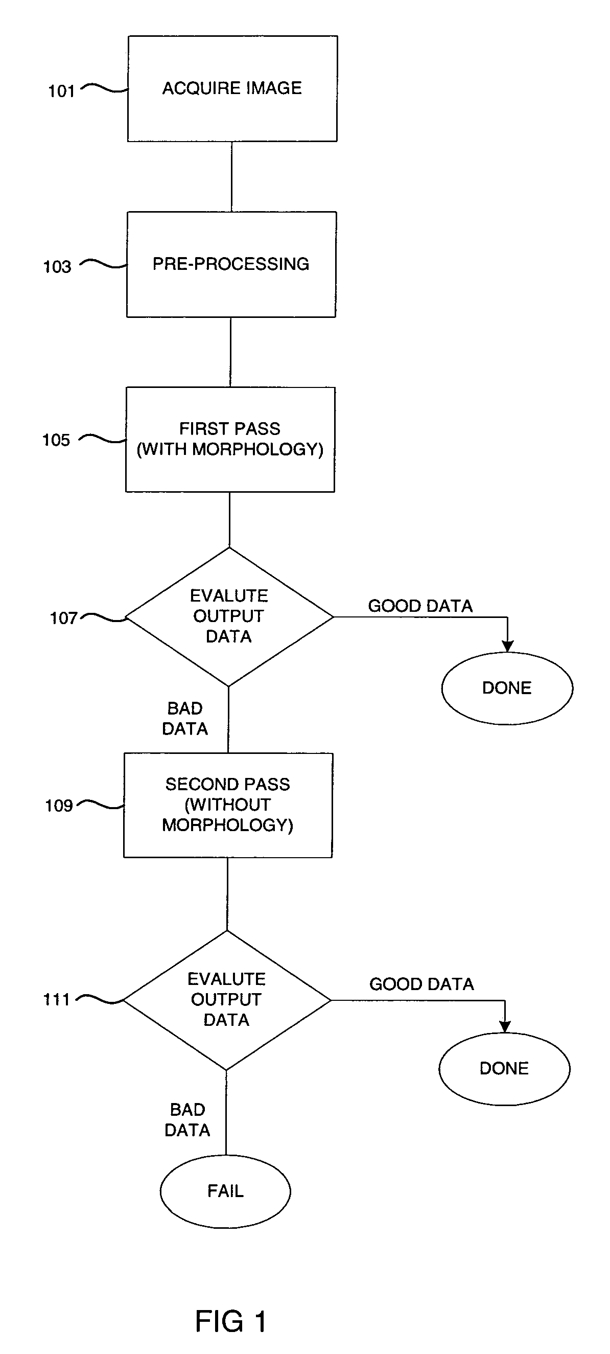
[0026]The apparatus and method according to the invention perform a flexible image analysis for robust decoding of symbolic data. As shown in FIG. 1, digitized images are acquired 101, pre-processed 103 to create a morphology image, and a first pass is made 105 to decode the symbol data. If the output data is not valid 107, a second pass is made 109 without the morphology, and the output data is again evaluated 111.

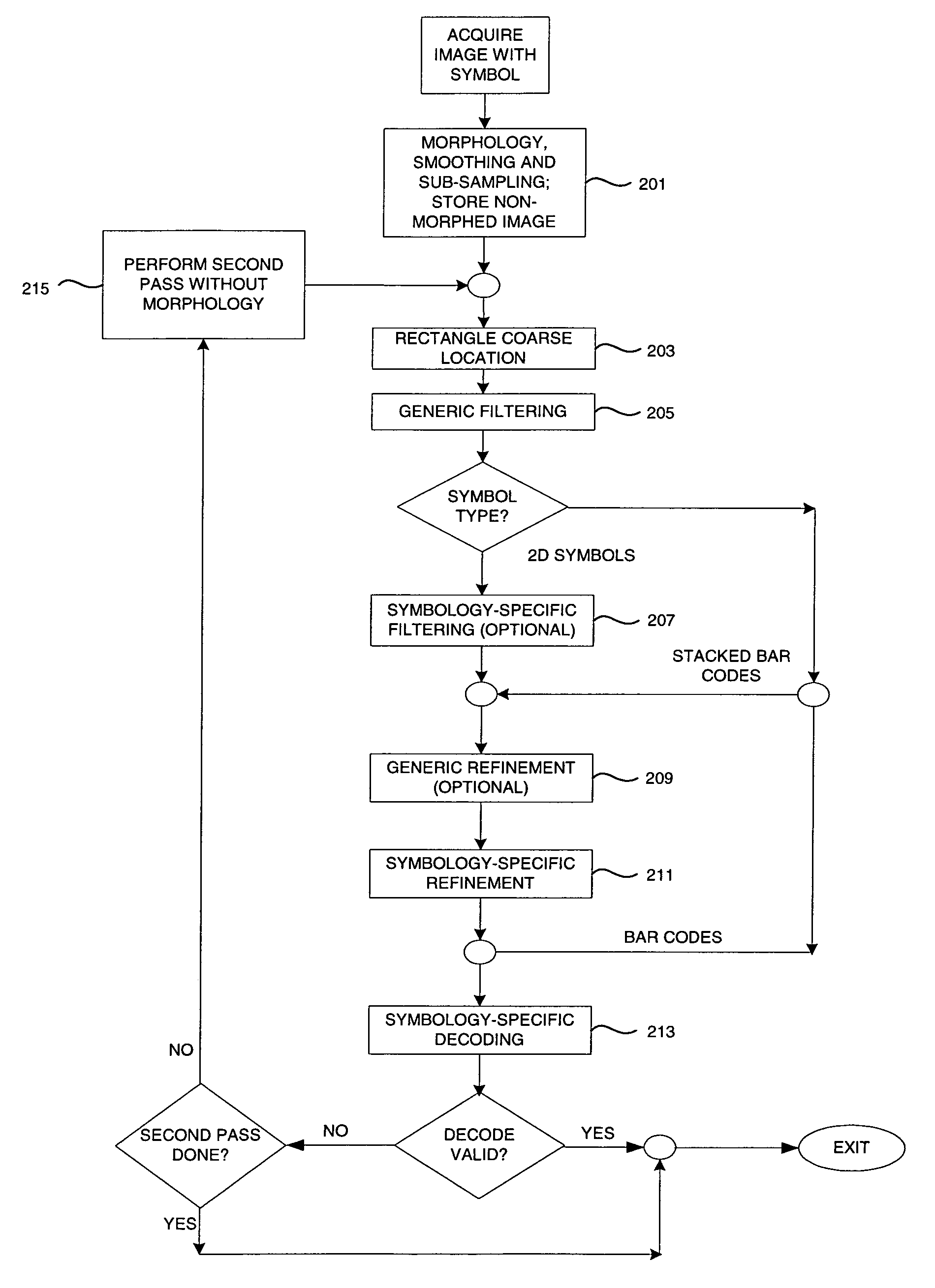
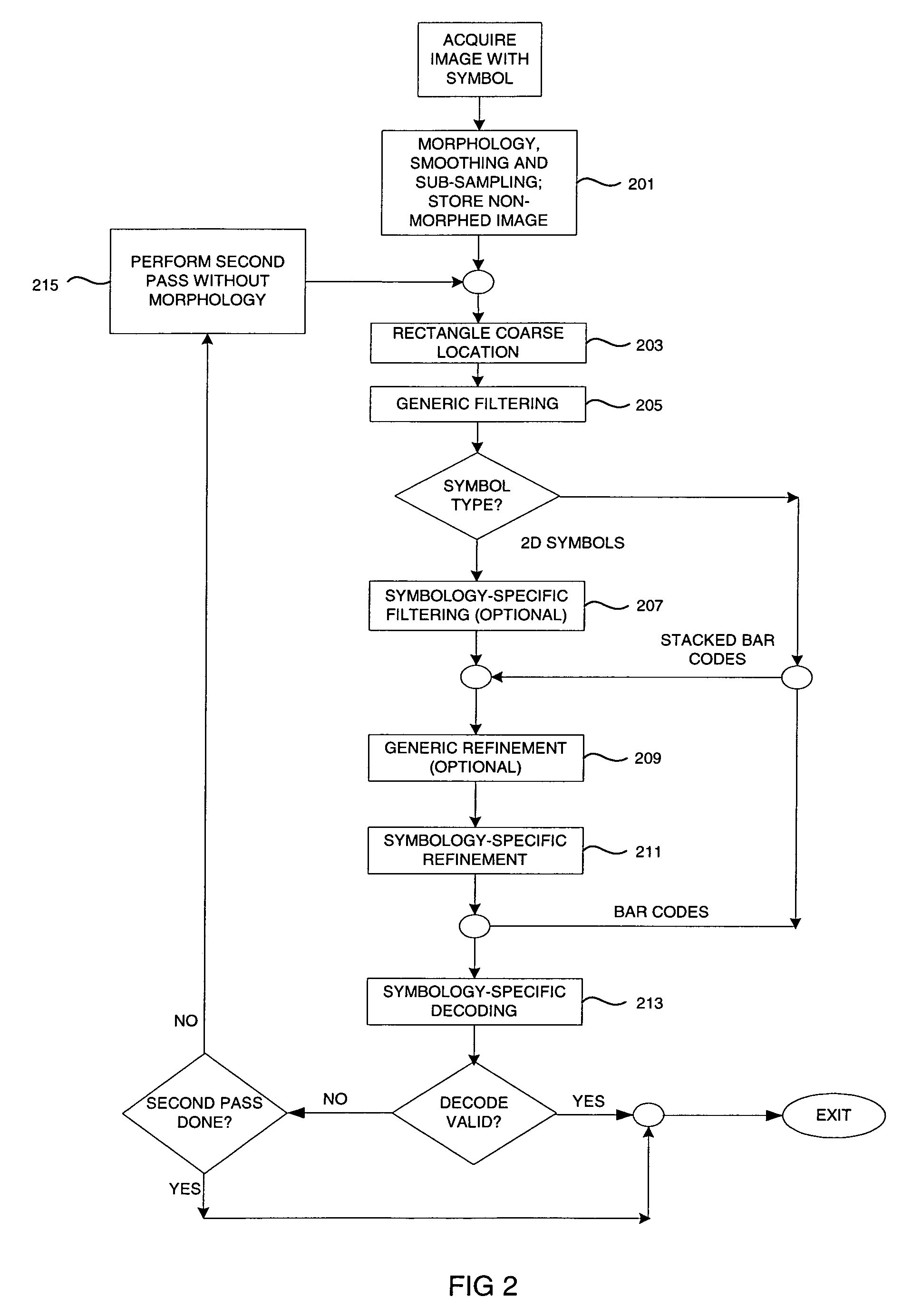
[0027]As shown in FIG. 2, during each pass, after preprocessing 201, a coarse symbol location is found 203, and its data is filtered 205. Then, depending upon the selected symbol type, additional symbol-specific filtering 207 and generic refinement 209 and / or symbology-specific refinement 211 are imposed, if necessary. If the data cannot be decoded as valid 213, then the non-morphed image is retrieved 215 and another pass is made, resulting in either a valid decode or a failure result.

[0028]The image acquisition step 101 can be accomplished using apparatus and methods kno...


PUM


Abstract

Visual information regarding intensity and intensity-based gradient information is used in a multi-step process for accurately locating and decoding an encoded visual symbol matrix. A symbol is preprocessed with filtering and morphology. A set of coarse locations of candidate symbols is filtered according to coarse geometric criteria to determine which image locations are most viable. Depending upon the symbol type, and information about the edges of the symbols, additional symbol-specific filtering and refinements can be applied or skipped. For 2D matrices filtering according to intensity variance criteria is followed by an edge-locating refinement and by identifying finder patterns and timing patterns. Once finder patterns and timing patterns are precisely located, the data region is decoded. Where a data region does not decode validly, another pass is run, using the non-morphed image, resulting in an overall saving of time, as rejections may require operator intervention.

Description

FIELD OF INVENTION[0001]The present invention relates to industrial vision systems, particularly vision systems for recognition and interpretation of encoded graphical information.BACKGROUND[0002]Two-dimension (2D) matrix symbols are becoming increasingly popular in automated identification applications due to their compact size, large data capacity and their built-in error checking and correction. The encoded information is represented as a binary pattern arranged as a 2D matrix of lines, dots or squares. Characteristic patterns are appended to the 2D matrix to allow the matrix to be located and distinguished easily during decoding. These factors allow the appropriate 2D symbology to be used in specific ID applications such as semiconductor wafer marking and document labels.[0003]For example, the Data Matrix symbology, is a popular choice in wafer ID applications, as described in the International Symbology Specification—Data Matrix, AIM International, Inc. which is incorporated he...

Claims


Application Information

Patent Timeline
IPC IPC(8): G06K9/56G06K9/40G06K9/54G06K7/14
CPCG06K7/14G06K7/1443
Inventor NADABAR, SATEESH GOPALAKRISHNADESAI, RANJIT
Owner COGNEX CORP
Why Eureka
Try Eureka