Interconnecting method for segmented stator electric machines

Inactive Publication Date: 2005-09-13
HERMETIC MOTORS LP
View PDF27 Cites 12 Cited by
  • Summary
  • Abstract
  • Description
  • Claims
  • Application Information

AI Technical Summary

Problems solved by technology

This approach has relatively high labor cost.
Both PCBs and IDCs have a relatively high cost.
PCBs also have limited heat dissipation, which may pose a problem for low voltage

Method used


Image

  • Interconnecting method for segmented stator electric machines
  • Interconnecting method for segmented stator electric machines
  • Interconnecting method for segmented stator electric machines

Examples


Embodiment Construction

[0025]The following description of the preferred embodiment(s) is merely exemplary in nature and is in no way intended to limit the invention, its application, or uses. For purposes of clarity, the same reference numbers will be used in the drawings to identify similar elements.

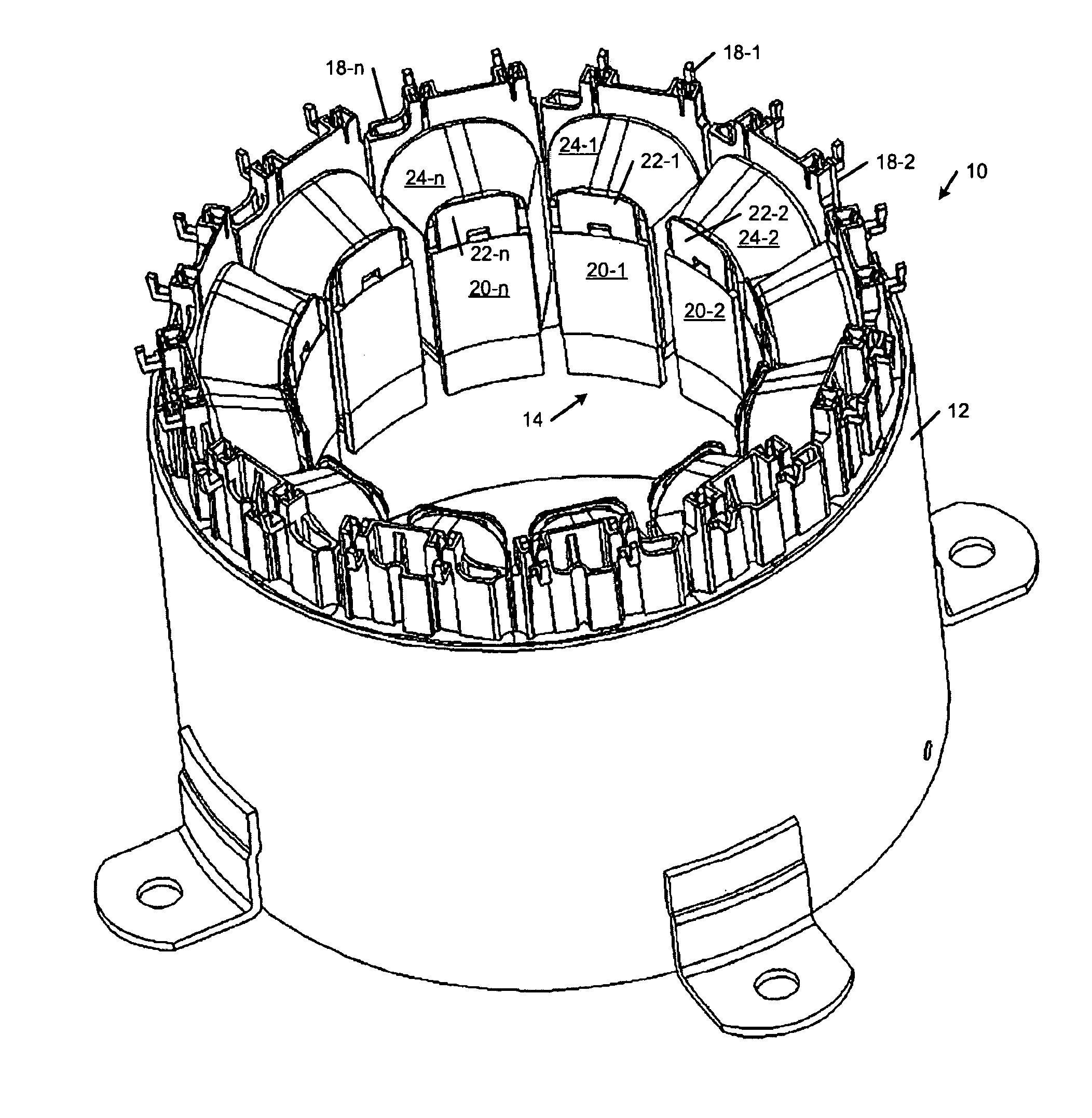
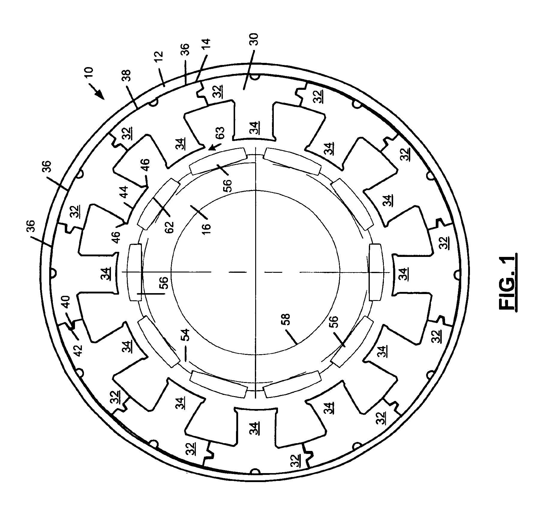
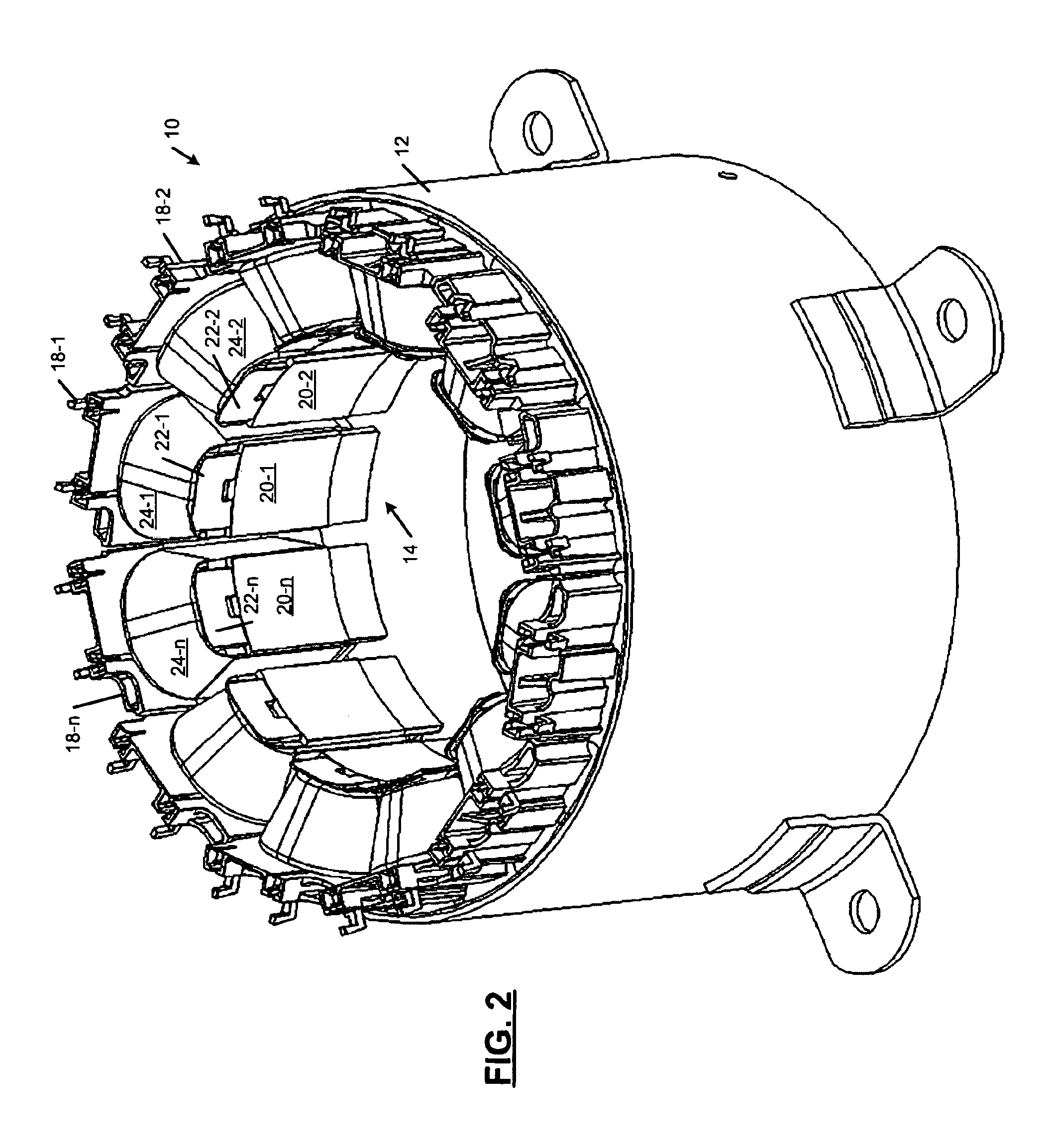
[0026]Referring now to FIG. 1, an exemplary brushless permanent magnet electric machine 10 is shown. The electric machine 10 includes a housing 12 and a segmented stator 14 mounted in the housing 12. A rotor 16 is supported for rotation relative to the segmented stator 14. While the present invention will be described in conjunction with brushless permanent magnet electric machines, the present invention may also be used with other types of segmented stator electric machines such as switched reluctance electric machines. For additional details concerning segmented stator switched reluctance electric machines, see U.S. Pat. Ser. Nos. 09 / 803,876, Filed Mar. 12, 2001, “Segmented Stator Switched Reluctance Machin...


PUM


Abstract

A method of connecting phases of a segmented stator electric machine includes providing a stator core. An end cap assembly is attached to the stator core. Winding wire is wound around the end cap assembly and the stator core to form a stator segment assembly. A plurality of the stator segment assemblies are assembled into a stator including first, second and third phases. A phase wire stitching machine is used to connect opposite ends of the winding wire of each of the stator segment assemblies to form the first, second and third phases of the stator. The phase wires can be attached to the stator segment assemblies using terminals, IDCs, hook terminals, and/or directly to the winding wire.

Description

FIELD OF THE INVENTION[0001]The present invention relates to electric machines, and more particularly to an improved interconnection method for phase wires of a segmented stator electric machine.BACKGROUND OF THE INVENTION[0002]Electric machines, such as motors and generators, typically include a stator that is mounted inside a housing and a rotor that is supported for rotation relative to the stator. There are several conventional methods for placing the winding wire on the stator teeth of non-segmented electric machines. A transfer winding method involves initially winding the wire and then transferring the pre-wound wire onto the stator teeth. Transfer winding tends to leave excess winding wire or loops around axial ends of the stator teeth. Transfer winding can typically utilize approximately 60-65% of available stator slot area.[0003]When multiple phases of the electric machine are interconnected using transfer winding, the winding wire for teeth associated with one polarity of...

Claims


Application Information

Patent Timeline
IPC IPC(8): H02K3/52H02K3/46H02K15/00
CPCH02K3/522H02K15/0056H02K15/0075H02K2203/03Y10T29/49009Y10T29/49011Y10T29/53157Y10T29/49169Y10T29/49174Y10T29/49012Y10T29/49078H02K15/0068H02K3/52H02K5/22
Inventor HARTSFIELD, JR., RICHARD E.HORST, GARY E.HURST, DENNIS M.SHEERAN, KENT A.
Owner HERMETIC MOTORS LP
Why Eureka
Try Eureka