Injection molding method and apparatus with reduced piston leakage

a technology of injection molding and pistons, applied in the direction of metal founding, chemistry apparatus and processes, etc., can solve the problems of metal leaking backwards past the piston or screw, the inability to manufacture an apparatus without some clearance between the piston or screw and the inner wall of the injection chamber, and the driving mechanism of the piston or screw

Inactive Publication Date: 2005-09-13
TAKATA CORPORATION
View PDF152 Cites 16 Cited by
  • Summary
  • Abstract
  • Description
  • Claims
  • Application Information

AI Technical Summary

Benefits of technology

[0009]Another preferred embodiment of the present invention provides an injection molding apparatus, comprising a piston comprising a head and a shaft, the shaft having a diameter smaller than a diameter of the head, a first injection chamber portion having a front end, a back end and a cavity having a circular internal cross section and containing the piston head. The apparatus further comprises a second injection chamber portion joined to the back end of the first chamber portion, the second chamber portion having a front end, a back end and a cavity having a polygonal internal cross section and containing the piston shaft, at least one opening in at least one side wall of the second i

Problems solved by technology

Although conventional liquid metal injection molding and thixotropic metal injection molding have been used successfully in the past, conventional machines suffer from metal leaking backwards past the piston or screw into the drive mechanism, rather than being injected forward into the mold.
This occurs b

Method used


Image

  • Injection molding method and apparatus with reduced piston leakage
  • Injection molding method and apparatus with reduced piston leakage
  • Injection molding method and apparatus with reduced piston leakage

Examples


first embodiment

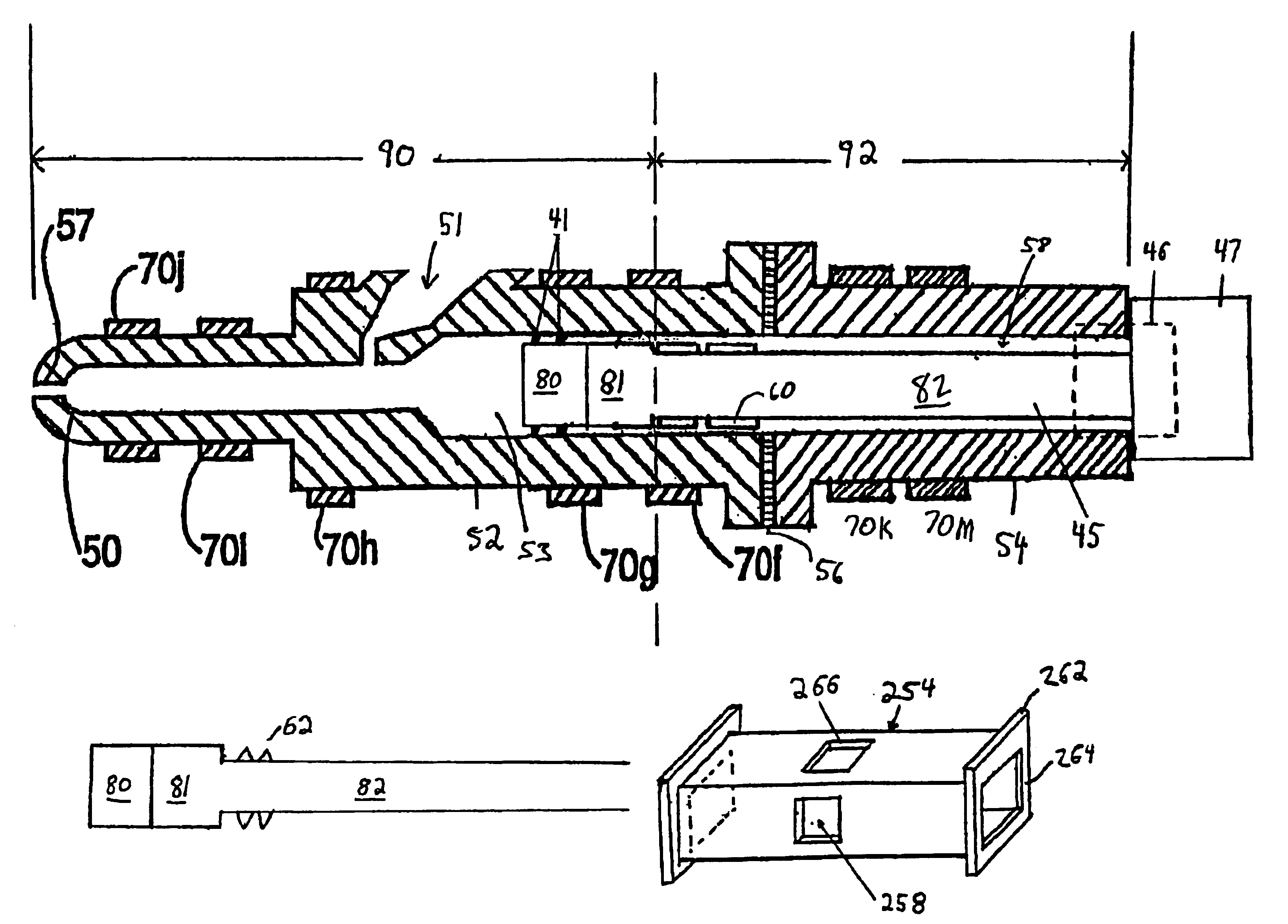
[0026]Another preferred aspect of the invention is illustrated in FIG. 1b. In this embodiment, the rings 62 have a roughly triangular cross section. Thus, the portions of the rings 60 adjacent to the shaft 82 are wider than the portions distal from the shaft 82. Preferably, the rings have sharp or pointed tips (i.e. portions distal from the shaft 82). This cross section aids both in trapping metal flowing through the shaft housing toward the drive mechanism and in the removal of solidified metal adhered to the inner wall of the injection chamber.

[0027]In another alternative, and less preferred aspect of the first embodiment, the rings 60 are attached to or comprise portions of the injection chamber (i.e., protrusions on the inner wall of the injection chamber). In this case, the rings 60 are positioned in the shaft housing portion of the injection chamber 50 and do not move with the shaft. In this aspect of the invention, the shaft 82 has a smaller outer diameter than the inner diam...

second embodiment

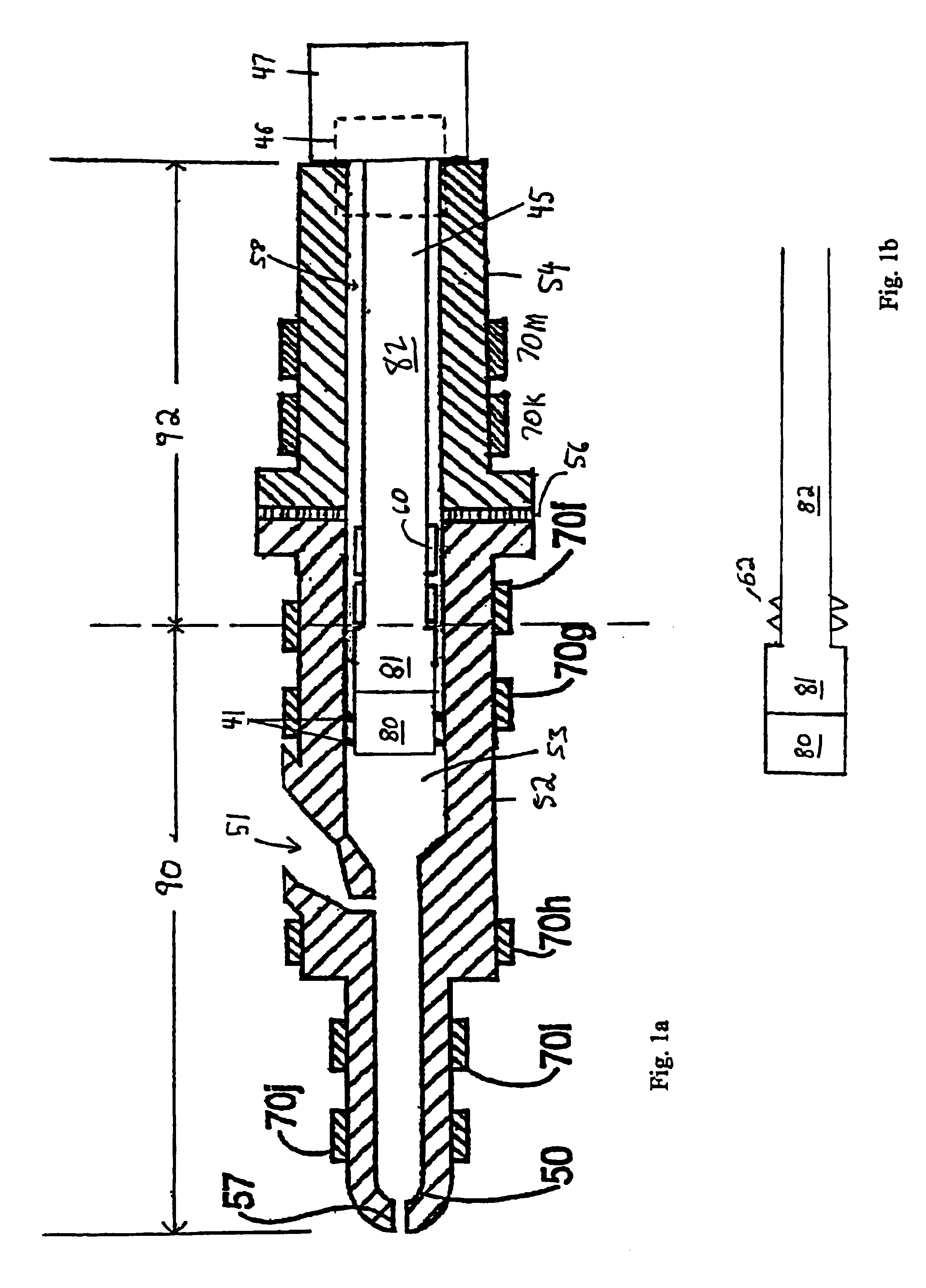
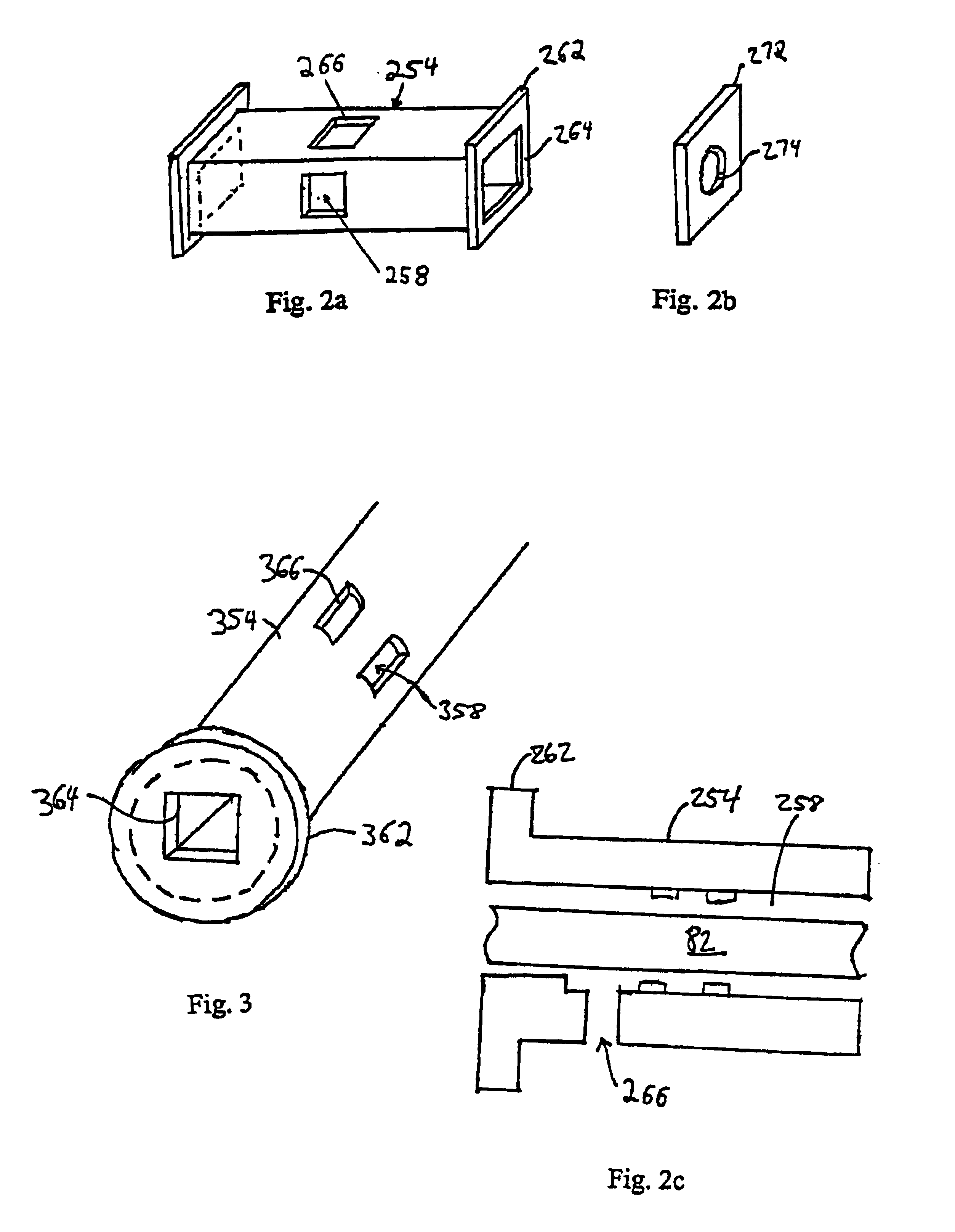
[0035]At either end of the shaft housing 254, there are flanges 262. One of the flanges can be attached to a corresponding flange on the end of the accumulation portion 52 of the injection chamber 50. The other flange may be attached to the drive mechanism 47. The flanges may be bolted, welded, clamped or affixed in any suitable manner. If an optional insulating gasket 56 is included, it is preferable to bolt the chambers together. A shaft hole 264 is included in the flanges 262. In this aspect of the invention, the shaft hole 264 is square. FIG. 2b illustrates a second aspect of the invention. In this aspect, the shaft hole 274 is circular. In additional aspects of the invention, the shaft hole 274 may be of any shape including, for example, rectangular, hexagonal and octagonal.

[0036]FIG. 3 illustrates another preferred design of a shaft housing 354. In this design, the shaft housing 354 has a cylindrical outside wall and a cavity 358 with a square or other polygonal cross section....


PUM

PropertyMeasurementUnit
Temperatureaaaaaaaaaa
Diameteraaaaaaaaaa
Widthaaaaaaaaaa

Abstract

A metal injection molding apparatus is provided with features which reduce the amount of metal which enters the drive mechanism of the apparatus. The apparatus contains a piston having the head and the shaft, the shaft having a diameter smaller than the diameter of the head. At least one piston ring circumscribes the piston shaft. The apparatus contains an injection chamber having an accumulation portion and a shaft housing portion. The shaft housing portion has openings in the sidewalls and a polygonal internal cross section. The accumulation portion of the injection chamber is maintained at a higher temperature than the shaft housing portion.

Description

[0001]This application is a continuation-in-part of application Ser. No. 09 / 842,092, filed Apr. 26, 2001, which is a divisional of application Ser. No. 09 / 330,147, filed Jun. 11, 1999, which is a divisional application Ser. No. 09 / 160,792, filed Sep. 25, 1998, now U.S. Pat. No. 5,983,976, which claims the benefit of U.S. Provisional Application No. 60 / 080,078, filed Mar. 31, 1998, which are hereby incorporated by reference in their entirety.FIELD OF THE INVENTION[0002]The present invention is directed generally to injection molding methods and machines and more particularly to a device and method for reducing the leakage of liquid past the piston in an injection molding machine.BACKGROUND OF THE INVENTION[0003]One conventional method used to produce molded metal alloys is the die cast method. In this method, the metal to be injected is heated above its liquidus temperature and then forced into the mold by the extension of a piston in the injection chamber. Another conventional metho...

Claims


Application Information

Patent Timeline
IPC IPC(8): B22D17/00B22D17/30B29C45/53
CPCB22D17/007B22D17/30B29C45/53Y10S164/90
Inventor KONO, KANAME
Owner TAKATA CORPORATION
Why Eureka
Try Eureka