Oil-less/oil-free air brake compressor with a dual piston arrangement

a dual-piston arrangement and compressor technology, applied in the field of compressors, can solve the problems of contaminating the air brake system, not inhibiting the oil thrown from the crankshaft from entering, and the system that accommodates the air compressor does not permit the mere addition of similar pistons

Inactive Publication Date: 2000-09-05
ALLIEDSIGNAL TRUCK BRAKE SYST
View PDF11 Cites 31 Cited by
  • Summary
  • Abstract
  • Description
  • Claims
  • Application Information

AI Technical Summary

Problems solved by technology

For example, commercial arrangements usually employ five (5) piston rings that, although seal the compression chamber, do not inhibit sufficiently oil thrown from the crankshaft from entering...

Method used


Image

  • Oil-less/oil-free air brake compressor with a dual piston arrangement
  • Oil-less/oil-free air brake compressor with a dual piston arrangement
  • Oil-less/oil-free air brake compressor with a dual piston arrangement

Examples


Embodiment Construction

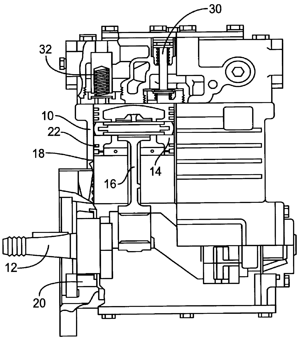
Turning first to FIG. 1, and by way of introducing common terms used in the following description of the preferred embodiments of the invention, a conventional two cylinder, single stage, reciprocating compressor is illustrated and identified as prior art. A crankcase 10 houses the crankshaft 12, pistons 14 (only one of which is shown in cross-section), connecting rod 16, cylinder bore 18, and main bearings 20. As is known, the piston includes piston rings 22 on the peripheral surface thereof adapted to sealingly engage the internal wall defining the cylinder bore. The crankshaft is driven by the vehicle engine and typically operates in a continuous mode when the engine is running. Actual compression of air, however, is controlled by the compressor unloading mechanism and the governor (not shown).

During a downstroke of the piston, inlet valve 30 opens to draw atmospheric air into the cylinder or chamber. As the piston begins its upward stroke, the inlet valve closes and the air is c...


PUM


Abstract

A cylinder is divided into two chambers by a wall to receive a pair of pistons. This reduces the stroke length and correspondingly reduces the linear speed of the piston. This leads to a reduced PV factor associated with degradation and wear of the piston rings. Moreover, the multi-cylinder arrangement provides the same performance in an oil-free compressor assembly without appreciably expanding dimensional constraints relative to known systems.

Description

1. Field of the InventionThis invention relates to compressors used in heavy vehicle braking systems. More particularly, the application is directed to an oil-less / oil free air compressor.2. Discussion of the ArtAir compressors are used in brake systems to provide and maintain air under pressure to operate the vehicle brakes and any auxiliary air systems. The compressor is engine driven and typically is a two cylinder, single stage, reciprocating compressor. A connecting rod extends from the engine driven crankshaft and is operatively connected to a piston that reciprocates in an associated bore to compress the air in the bore and provide pressurized air to the brake system / auxiliary air system.The vehicle engine provides a continuous supply of oil to the compressor. The oil is routed from the engine to an oil inlet of the compressor to maintain lubrication of connecting rod and crankshaft bearings, piston rings and other dynamic components. The pistons typically include a plurality...

Claims


Application Information

Patent Timeline
IPC IPC(8): F04B27/00
CPCF04B27/005
Inventor DUNAEVSKY, VALERYGILBERT, GENE
Owner ALLIEDSIGNAL TRUCK BRAKE SYST
Why Eureka
Try Eureka