Spring mass damper system for turbine shrouds

a damper system and turbine shroud technology, applied in the field of damping systems, can solve the problems of difficult attachment and ceramic composites, and achieve the effects of reducing heat load on the damper block, enhancing the long-term wear capability of the coupling, and reducing the damage of the vibratory respons

Inactive Publication Date: 2005-09-13
GENERAL ELECTRIC CO
View PDF6 Cites 41 Cited by
  • Summary
  • Abstract
  • Description
  • Claims
  • Application Information

AI Technical Summary

Benefits of technology

[0003]In accordance with an aspect of the present invention, there is provided an attachment mechanism between a ceramic composite shroud and a metallic support structure which utilizes the pressure distribution applied to the shroud, coupled with a loading on the shroud to tune the shroud to minimize damaging vibratory response from pressure pulses of the hot gases as the buckets pass the shrouds. To accomplish the foregoing, and in one aspect thereof, there is provided a spring mass damping system which includes a ceramic composite shroud / damping block, a damper load transfer mechanism and a damping mechanism. The damper block includes at least three projections for engaging the backside of the shroud, thereby spacing the damper block surface from the backside of the shroud, affording a convective insulating layer, and reducing heat load on the damper block. The three projections are specifically located along the damper block to tune the dynamic response of the system. The load transfer mechanism includes a piston having a ball-and-socket coupling with the damper block along with a spring damping mechanism in the socket region of the outer shroud block. The ball-and-socket coupling uses a pin retention system enabling relative movement between the piston and damper block. Local film cooling is also provided to enhance the long-term wear capability of the coupling. The piston engages the spring through a thermally insulating washer and preferably also through a metallic washer, both being encapsulated within a cup supplied with a cooling medium. The cooling medium maintains the temperature of the spring below a temperature limit in order to maintain positive preload on the shroud. Various other aspects of the present invention will become clear from a review of the ensuing description.
[0004]In a preferred embodiment according to the present invention, there is provided a damper system for a stage of a turbine comprising a shroud having a first surface defining in part a hot gas path through the turbine, a shroud body for supporting the shroud, a damper block having at least three projections raised from a surface thereof and engaging a backside surface of the shroud opposite the first surface and a damping mechanism carried by the shroud body and connected to the damper block for applying a load to the damper block and the shroud through the engagement of the projections with the backside surface of the shroud thereby damping vibratory movement of the shroud.
[0005]In a further preferred embodiment according to the present invention, there is provided a damper system for a stage of a turbine comprising a shroud formed of a ceramic material having a first surface defining in part a hot gas path through the turbine, a shroud body for supporting the shroud, a damper block carried by the shroud body and engaging the shroud, the damper block being formed of a metallic material and a damping mechanism carried by the shroud body and connected to the damper block for applying a load to the damper block and the shroud to dampen vibratory movement of the shroud, the damping mechanism including a spring for applying the load to the damper block.

Problems solved by technology

Moreover, because of this proximity to high-speed rotation of the buckets, the vibration may be at or near resonant frequencies and thus require damping to maintain life expectancy during long-term commercial operation of the turbine.
Ceramic composites, however, are difficult to attach and have failure mechanisms such as wear, oxidation due to ionic transfer with metal, stress concentration and damage to the ceramic composite when configuring the composite for attachment to the metallic components.

Method used


Image

  • Spring mass damper system for turbine shrouds
  • Spring mass damper system for turbine shrouds
  • Spring mass damper system for turbine shrouds

Examples


Embodiment Construction

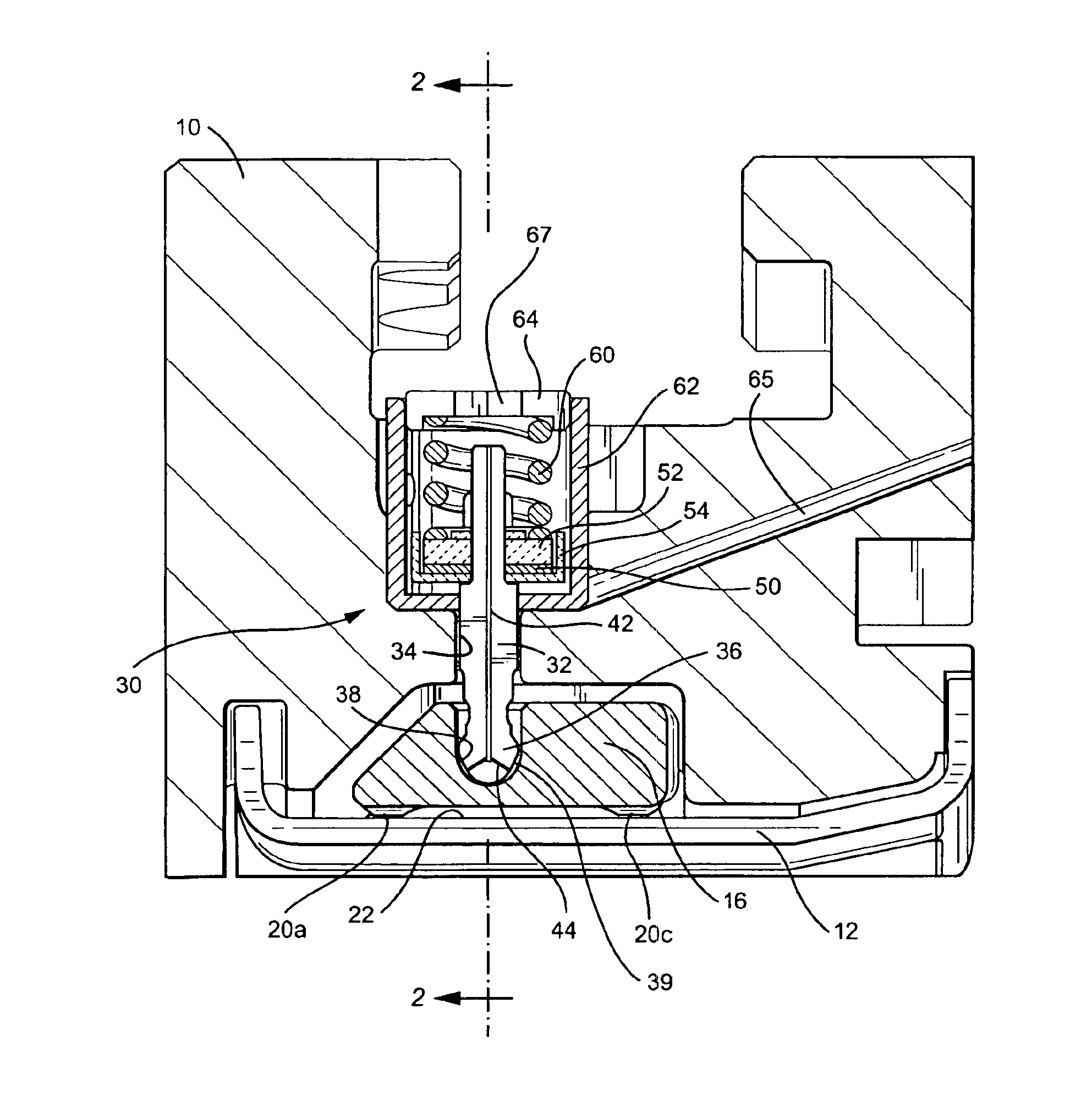
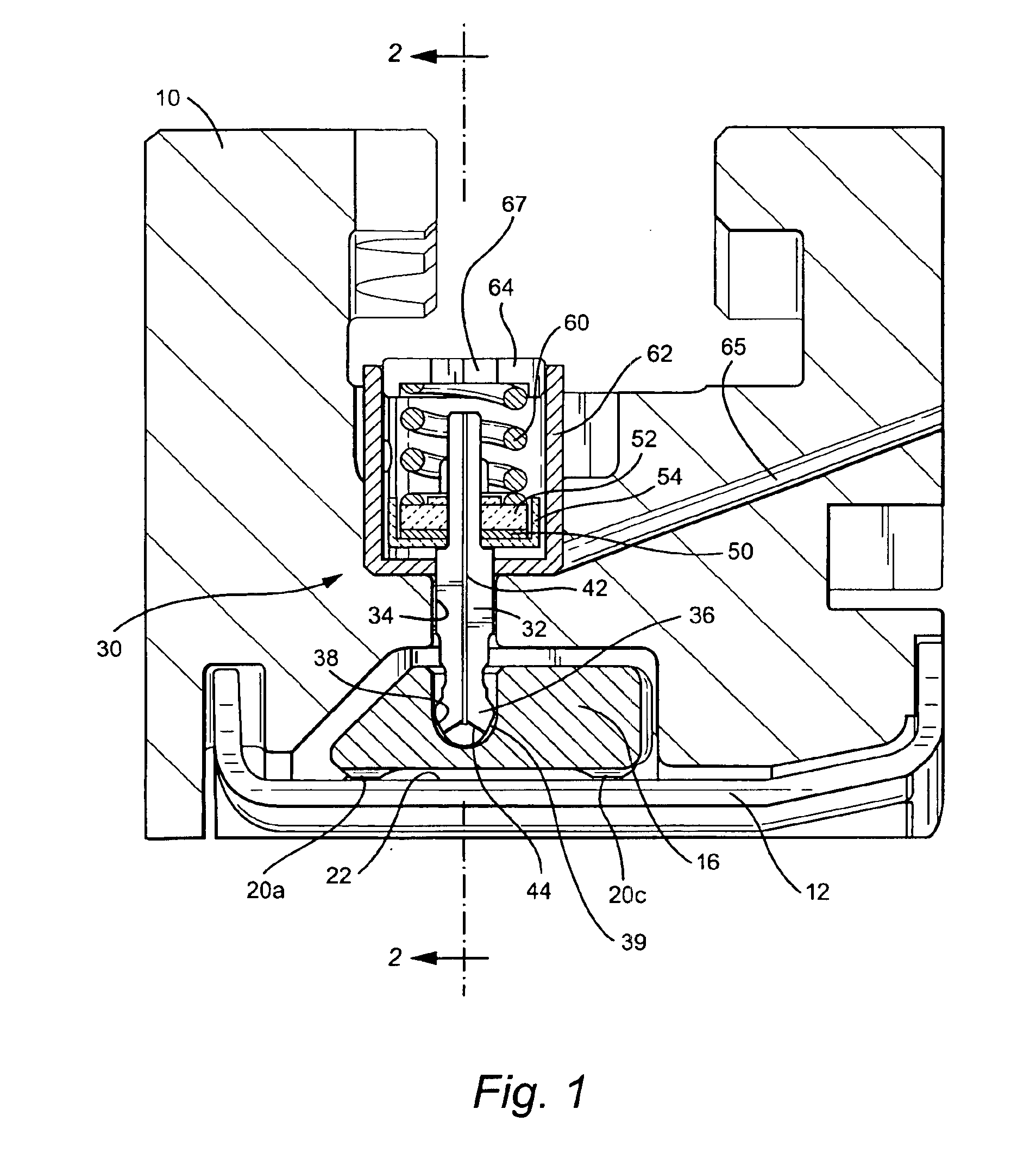
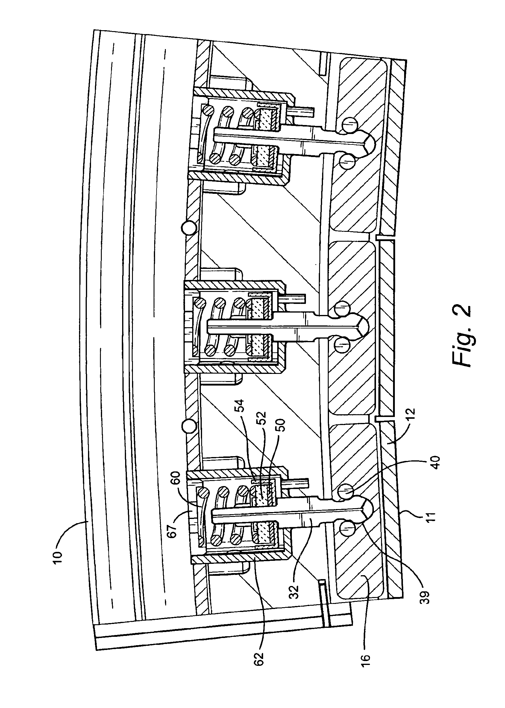
[0010]Referring now to FIGS. 1 and 2, there is illustrated an outer shroud block or body 10 mounting a plurality of shrouds 12. FIG. 1 is a view in a circumferential direction and FIG. 2 is a view in an axial forward direction opposite to the direction of flow of the hot gas stream through the turbine. As seen from a review of FIG. 2, the shroud block 10 carries preferably three individual shrouds 12. It will be appreciated that a plurality of shroud blocks 10 are disposed in a circumferential array about the turbine axis and mount a plurality of shrouds 12 surrounding and forming a part of the hot gas path flowing through the turbine. The shrouds 12 are formed of a ceramic composite, are secured by bolts, not shown, to the shroud blocks 10, and have a first inner surface 11 (FIG. 2) in contact with the hot gases of the hot gas path.

[0011]The damper system of the present invention includes a damper block / shroud interface, a damper load transfer mechanism and a damping mechanism. The...


PUM


Abstract

The damper system includes a ceramic composite shroud in part defining the hot gas path of a turbine and a spring-biased piston and damper block which bears against the backside surface of the shroud to tune the vibratory response of the shroud relative to pressure pulses of the hot gas path in a manner to avoid near or resonant frequency response. The damper block has projections specifically located to bear against the shroud to dampen the frequency response of the shroud and provide a thermal insulating layer between the shroud and the damper block.

Description

BACKGROUND OF THE INVENTION[0001]The present invention relates to a damping system for damping vibration of shrouds surrounding rotating components in a hot gas path of a turbine and particularly relates to a spring mass damping system for interfacing with a ceramic shroud and tuning the shroud to minimize vibratory response from pressure pulses in the hot gas path as each turbine blade passes the individual shroud.[0002]Ceramic matrix composites offer advantages as a material of choice for shrouds in a turbine for interfacing with the hot gas path. The ceramic composites offer high material temperature capability. It will be appreciated that the shrouds are subject to vibration due to the pressure pulses of the hot gases as each blade or bucket passes the shroud. Moreover, because of this proximity to high-speed rotation of the buckets, the vibration may be at or near resonant frequencies and thus require damping to maintain life expectancy during long-term commercial operation of ...

Claims


Application Information

Patent Timeline
Patent Type & Authority Patents(United States)
IPC IPC(8): F01D25/04F01D25/24F01D9/04F01D25/00F01D11/08F02C7/18F02C7/24F02C7/28
CPCF01D9/04F01D11/08F01D25/005F01D25/04F01D25/246
Inventor SCHRODER, MARK STEWARTCAIRO, RONALD RALPHGRACE, CHRISTOPHERWETZEL, TODD GARRETTBRUCE, KEVIN LEONMILLER, ANDREW WILLIAMNIMMER, RONALD PHILLIP
Owner GENERAL ELECTRIC CO
Why Eureka
Try Eureka