Backlight assembly and liquid crystal display apparatus having the same

a backlight assembly and liquid crystal display technology, applied in lighting and heating apparatus, planar/plate-like light guides, instruments, etc., can solve the problems of deteriorating increased weight of the lcd apparatus, so as to improve the light efficiency prevent an increase in the thickness of the backlight assembly. , the effect of efficient light emission

Inactive Publication Date: 2005-09-13
SAMSUNG DISPLAY CO LTD
View PDF3 Cites 30 Cited by
  • Summary
  • Abstract
  • Description
  • Claims
  • Application Information

AI Technical Summary

Benefits of technology

[0022]According to the present invention, a linear distance between the reflecting surface and the emitting surface is smaller than a height of the incident surface. That is, an optical sheet is positioned at the emitting surface having a height lower than the height of the incident surface. Accordingly, although the height of the incident surface increases in association with a variation of size of the light source, the linear distance between the reflecting surface and the emitting surface does not need to increase. Therefore, the light guide plate can obtain an area of the incident surface appropriate to efficiently receive the light emitted from the light source, thereby improving a light efficiency of the backlight assembly and preventing an increase in a thickness of the backlight assembly.

Problems solved by technology

However, a backlight assembly has a higher power consumption and an LCD apparatus has an increased weight and an enlarged size due to the backlight assembly.
However, since the light-emitting diode cannot irradiate light to a long distant place, a light-emitting diode is mainly applied to a mobile LCD apparatus for medium and small size products having a small display screen.
As a result, a light efficiency of the backlight assembly 50 may be deteriorated.

Method used


Image

  • Backlight assembly and liquid crystal display apparatus having the same
  • Backlight assembly and liquid crystal display apparatus having the same
  • Backlight assembly and liquid crystal display apparatus having the same

Examples


Embodiment Construction

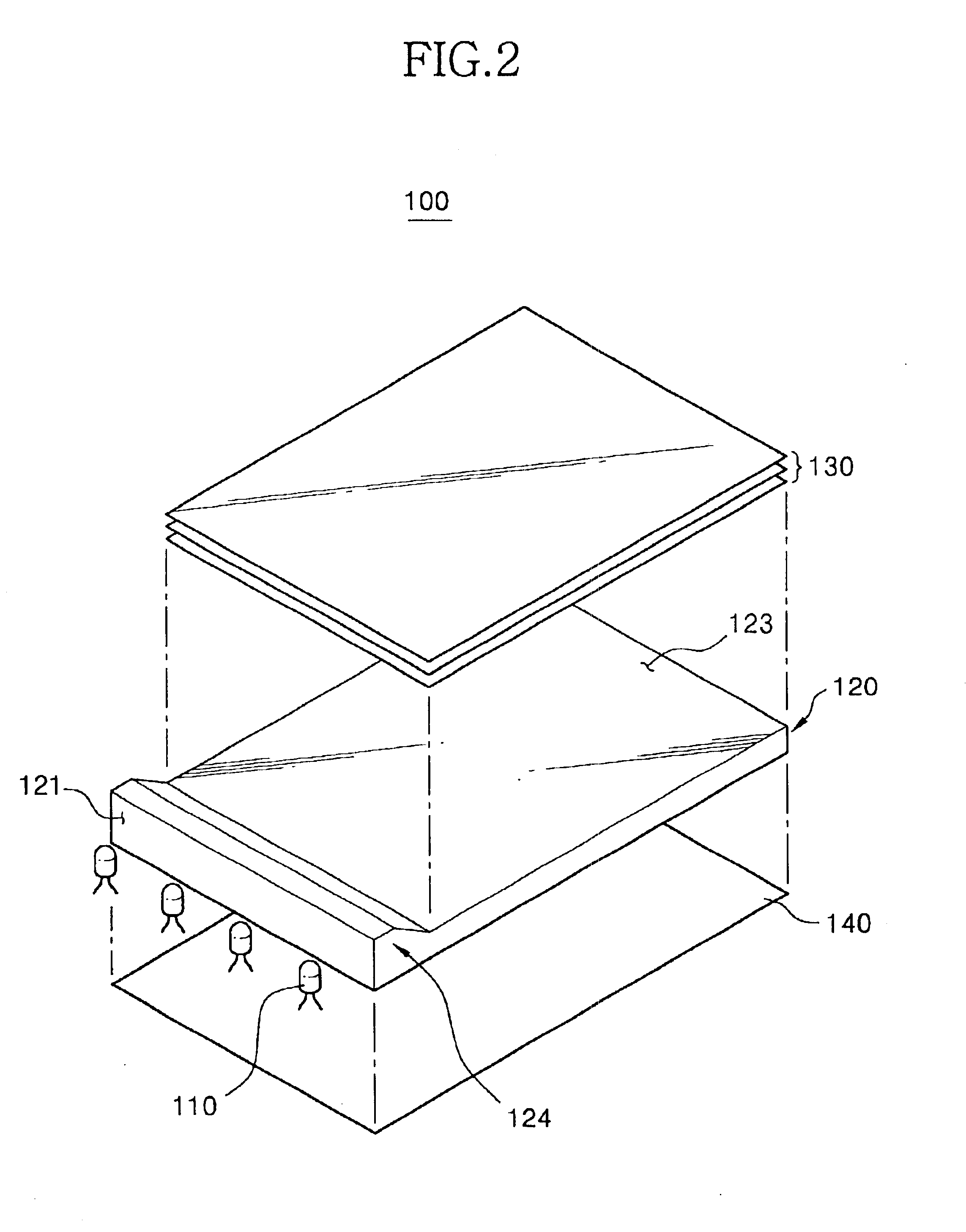
[0032]FIG. 2 is a perspective view showing a backlight assembly according to an exemplary embodiment of the present invention and FIG. 3 is a cross-sectional view showing the backlight assembly shown in FIG. 1.

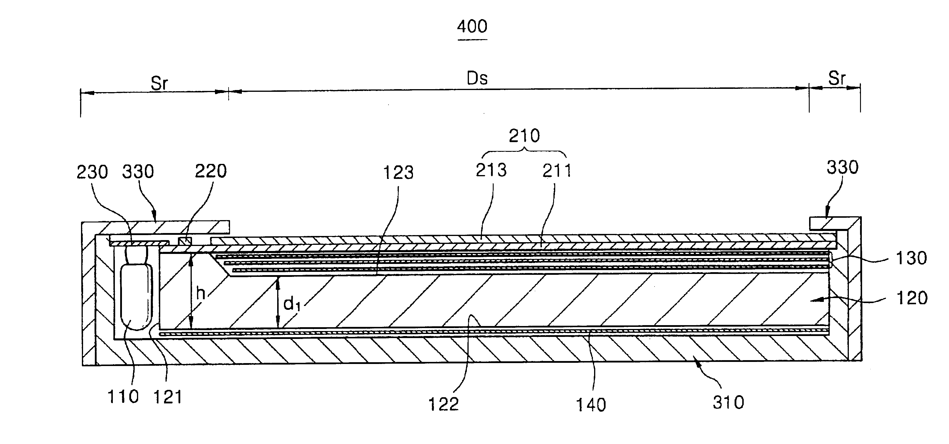
[0033]Referring to FIGS. 2 and 3, a backlight assembly 100 includes a light source 110 for generating light and a light guide plate120 for guiding the light so as to emit the light in a predetermined direction.

[0034]Particularly, the light source 110 has a point light source, for example, such as a plurality of light-emitting diodes and generates the light. Each of light-emitting diodes respectively emits the light with recombination of minority carriers, for example, such as electrons or holes injected by using a PN-junction structure of a semiconductor device.

[0035]The light guide plate 120 includes an incident surface 121 that receives the light emitted from the light source 110 and is disposed adjacent to the light source 110, a reflecting surface 122 that reflects the lig...


PUM

PropertyMeasurementUnit
interior angleaaaaaaaaaa
heightaaaaaaaaaa

Abstract

In an LCD apparatus having a backlight assembly, a light guide plate includes an incident surface for receiving light, a reflecting surface for reflecting the light and an emitting surface for emitting the light. A linear distance between the reflecting and emitting surfaces is smaller than a height of the incident surface. An optical sheet is positioned at the emitting surface having a height lower than the height of the incident surface. Accordingly, although the height of the incident surface increases, the linear distance between the reflecting and emitting surfaces does not increase. Therefore, the light guide plate can obtain an area of the incident surface appropriate to efficiently receive the light, thereby improving a light efficiency of the backlight assembly and preventing an increase in a thickness of the backlight assembly.

Description

CROSS-REFERENCE TO RELATED APPLICATION[0001]This application relies for priority upon Korean Patent Application No. 2002-77066 filed on Dec. 5, 2002, the contents of which are herein incorporated by reference in its entirety.BACKGROUND OF THE INVENTION[0002]1. Field of the Invention[0003]The present invention relates to a backlight assembly and an LCD (Liquid Crystal Display) apparatus, and more particularly to a backlight assembly for reducing a whole size thereof and improving a light efficiency and an LCD apparatus having the same.[0004]2. Description of the Related Art[0005]In general, an LCD apparatus includes a backlight assembly for generating light and an LCD panel for displaying an image in response to the light provided from the backlight assembly.[0006]However, a backlight assembly has a higher power consumption and an LCD apparatus has an increased weight and an enlarged size due to the backlight assembly.[0007]Recently, a point light source, for example such as a light-...

Claims


Application Information

Patent Timeline
Patent Type & Authority Patents(United States)
IPC IPC(8): F21V8/00G02B6/00F21Y103/00G02F1/1333G02F1/13357
CPCG02B6/002G02B6/0068G02F1/1335
Inventor LEE, KYOUNG-DON
Owner SAMSUNG DISPLAY CO LTD
Why Eureka
Try Eureka