NC program generating method, NC apparatus, computer memory product, and computer program product

a program and program technology, applied in the direction of programme control, total factory control, instruments, etc., can solve the problems of shortened life of cutting tools, damage or chipping of cutting tools, and difficulty for unskilled operators to achieve satisfactory and achieve high machining efficiency and accuracy

Inactive Publication Date: 2005-09-13
KAKINO YOSHIAKI +4
View PDF17 Cites 35 Cited by
  • Summary
  • Abstract
  • Description
  • Claims
  • Application Information

AI Technical Summary

Benefits of technology

[0010]The invention has been devised with considering the above-mentioned problems. An object of the invention is to provide a method for generating an NC program in which in an NC machine equipped with an end mill serving as a cutting tool, the movement of the end mill is replaced with a combination of canned cycles of simple operations similarly to the case of drilling and tapping, whereby the tool path of the end mill together with the feed rate in each portion of the tool path is optimized, and whereby high machining efficiency and accuracy are obtained. Another object of the invention is to provide an apparatus used in the implementation of the method and a computer program for implementing this method and recording medium storing the computer program.

Problems solved by technology

As such, it is difficult for unskilled operators to achieve satisfactory machining efficiency and accuracy.
Further, in case that an inappropriate NC program is prepared, this program can cause various problems such as: damage or chipping to the cutting tool; and shortened life of the cutting tool due to excessive wear.
Further, even when an NC program is carefully prepared by a skilled operator, the program does not necessarily have the best performance.
Thus, there has been the possibility of losing an opportunity of improving the machining performance.

Method used


Image

  • NC program generating method, NC apparatus, computer memory product, and computer program product
  • NC program generating method, NC apparatus, computer memory product, and computer program product
  • NC program generating method, NC apparatus, computer memory product, and computer program product

Examples


Embodiment Construction

[0029]The invention is described below with reference to the drawings.

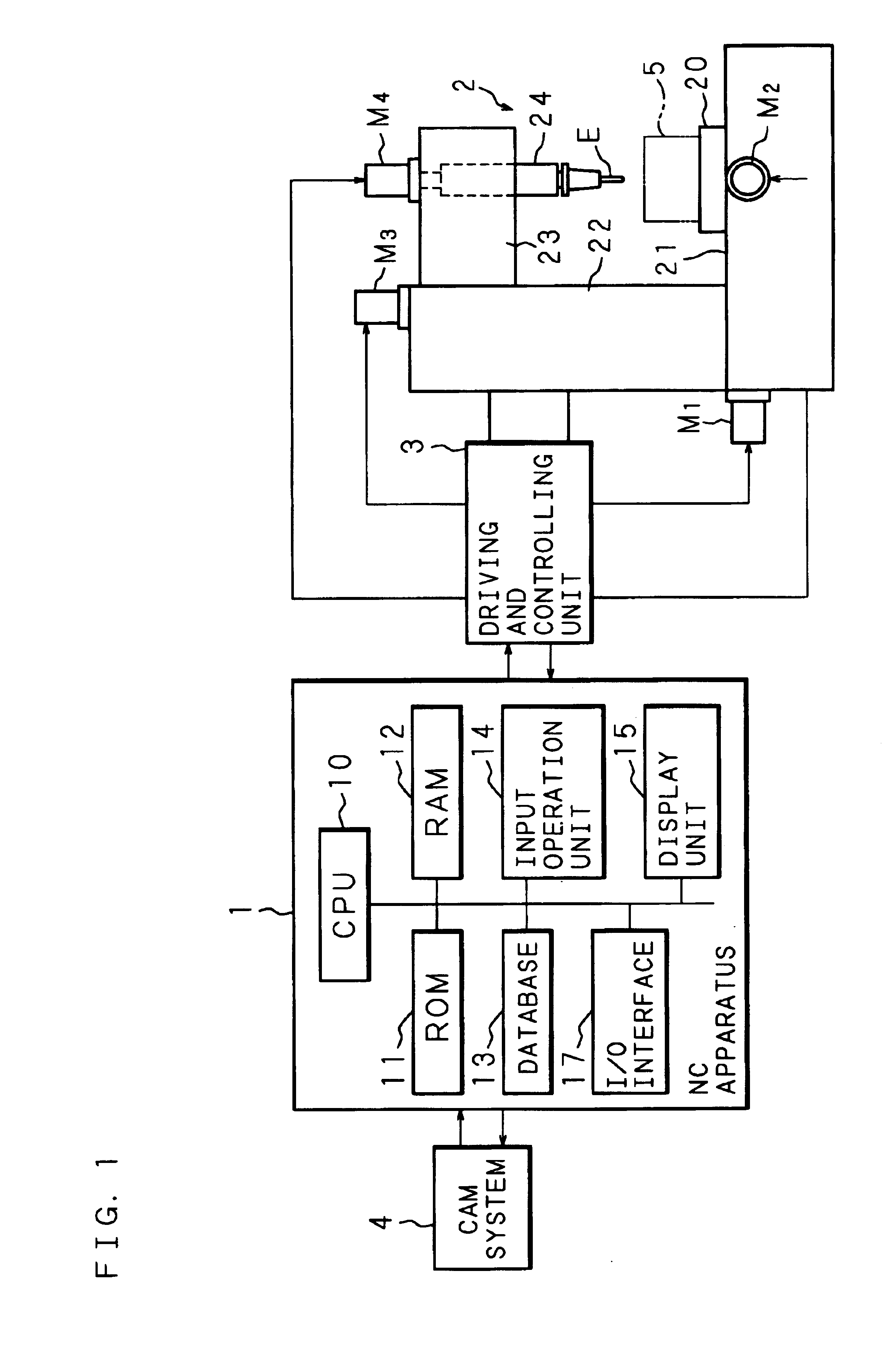
[0030]FIG. 1 is a block diagram showing the configuration of an NC machine comprising an NC apparatus used in the implementation of an NC program generating method according to the invention (a method according to the invention, hereafter). As shown in the figure, the NC apparatus 1 is composed of a computer comprising: a CPU (Central Processing Unit) 10 serving as an processing unit; a ROM (Read Only Memory) 11 for storing the procedures of the method according to the invention; a RAM (Random Access Memory) 12 for storing diverse variables necessary in the implementation of the method according to the invention (including values to be initially set and intermediate values during the calculations); and a database 13 referred to in the implementation of the method according to the invention. The NC apparatus 1 further comprises an input operation unit 14 composed of a keyboard, a mouse, and the like to be operated ...


PUM

PropertyMeasurementUnit
phase angleaaaaaaaaaa
feed rateaaaaaaaaaa
sizeaaaaaaaaaa

Abstract

An NC apparatus 1 replaces a required machining shape of a workpiece 5 with a predetermined canned machining cycle depending on a specification of machining conditions including a machining start point, a machining end point, and the size of an end mill E to be used. Calculation of an estimated value of cutting force exerted on the end mill E fed along the assumed tool path during the replaced canned machining cycle is repeated until a predetermined comparison and evaluation result is obtained in comparison with a predetermined appropriate value. Accordingly, the tool path of the end mill E together with the feed rate in each portion of the tool path is determined. This permits generation of an NC program which is used in a NC machine equipped with an end mill serve as a cutting tool, and which optimizes the tool path of the end mill together with the feed rate in each portion of the tool path such as to achieve high machining efficiency and accuracy.

Description

BACKGROUND OF THE INVENTION[0001]1. Field of the Invention[0002]The present invention relates to a method for generating an NC (numerical control) program which is used when an NC machine equipped with an end mill serving as a cutting tool cuts into a relatively simple shape, and which determines the tool path of the end mill together with the feed rate in each portion of the tool path such as to decrease wear and damage to the cutting tool and thereby permit as efficient and accurate cutting as possible. The present invention also relates to a computer program and a recording medium storing it.[0003]2. Description of the Related Art[0004]In NC machines for moving a cutting tool along a tool path defined in advance numerically relative to a workpiece fixed on a machining table and thereby machining the workpiece in a predetermined manner, in order to meet the requirements for improvements in machining efficiency and accuracy and for extended life of the cutting tool, it is important...

Claims


Application Information

Patent Timeline
Patent Type & Authority Patents(United States)
IPC IPC(8): B23Q15/12B23Q15/007B23Q15/00B23C5/10B23C1/00G05B19/4093
CPCG05B19/40937Y10T409/300896Y10T409/30112Y10T409/303808Y02P90/02
Inventor KAKINO, YOSHIAKINAKAGAWA, HEISABUROOHTSUKA, HIROTOSHI
Owner KAKINO YOSHIAKI
Why Eureka
Try Eureka