Connector

Active Publication Date: 2005-09-13
SUMITOMO WIRING SYST LTD
View PDF17 Cites 20 Cited by
  • Summary
  • Abstract
  • Description
  • Claims
  • Application Information

AI Technical Summary

Benefits of technology

[0007]The invention relates to a connector having first and second housings. The second housing has a receptacle for receiving the first housing. A movable member is mounted on the first housing for movement from an initial position to an ending position. A locking means also is provided for temporarily locking the movable member in the initial position. The movable member is formed with a cam means for engaging a mating cam means in the receptacle of the second housing. The cam means and the mating cam means cooperate for pulling the housings together as the movable member is moved from the initial position to the ending position. At least one unlocking rib projects from an inner surface of the receptacle. The unlocking rib cancels a locked state effected by the locking means when the first housing is fit lightly into the receptacle. Thus, the movable member can be moved from the initial position to the ending position, and the cam action of the cam means moves the housings into a properly connected condition.

Problems solved by technology

However, the insertion preventing rib prevents the first housing from being inserted into the receptacle in an improper posture

Method used


Image

  • Connector
  • Connector
  • Connector

Examples


Embodiment Construction

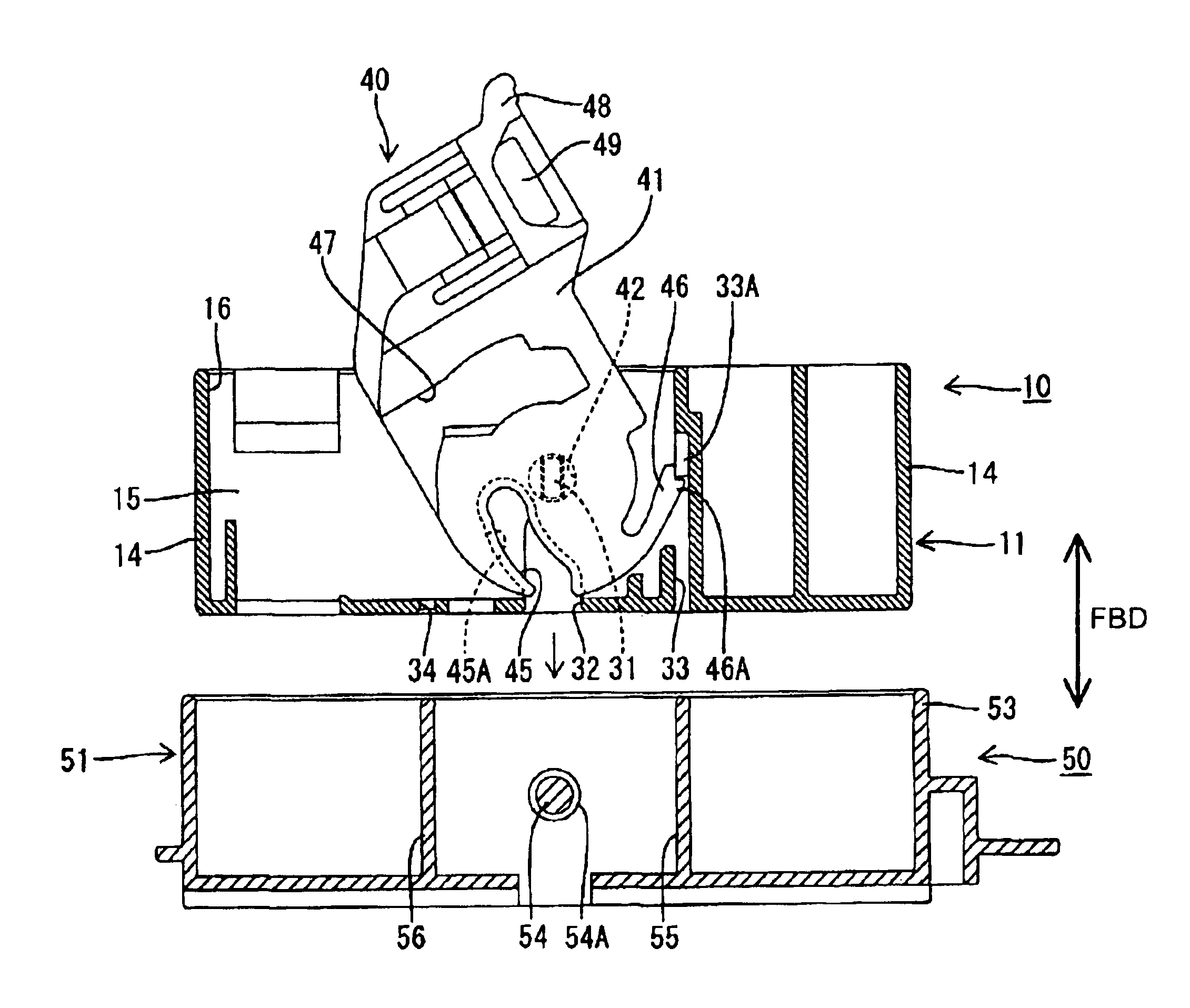
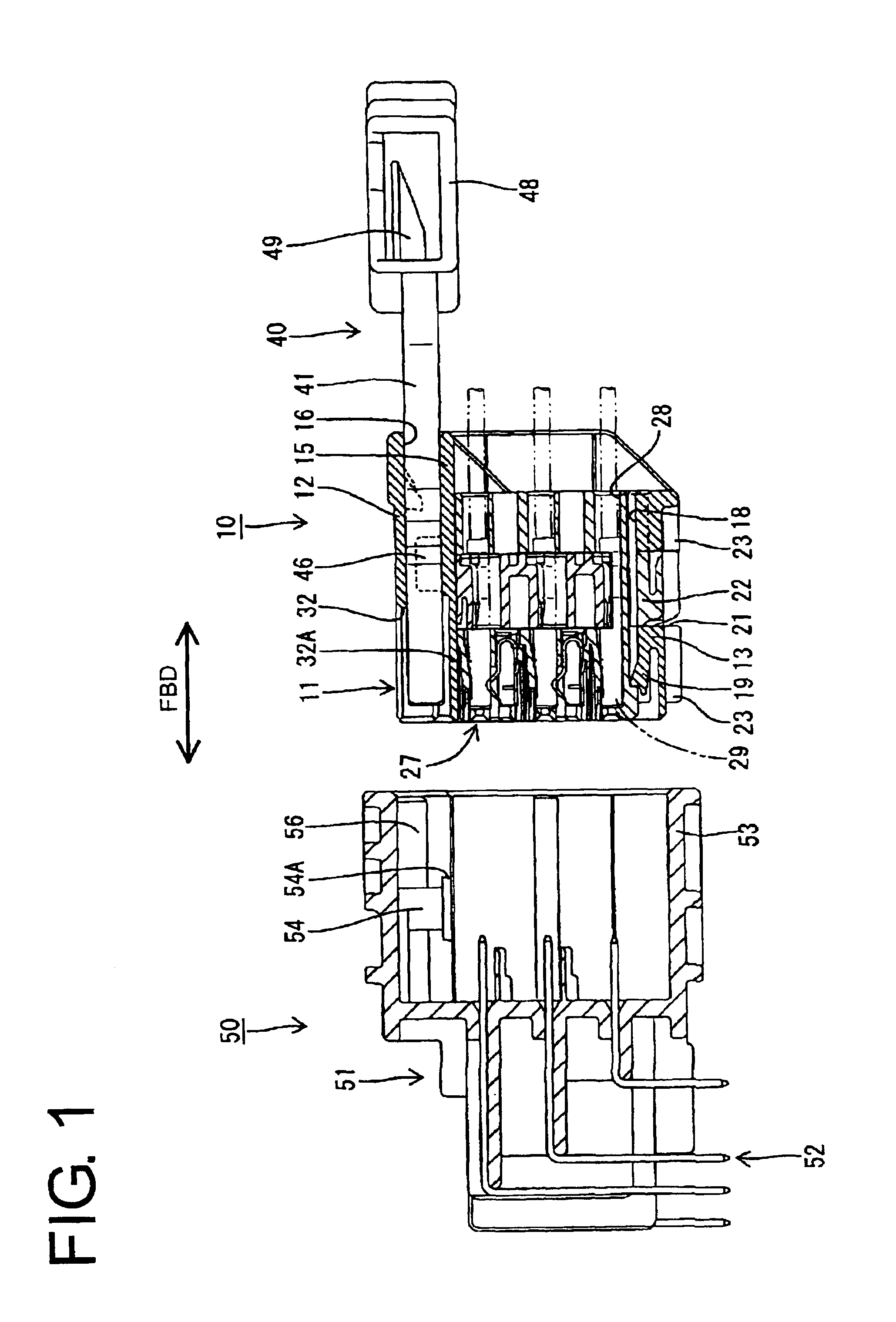
[0051]A lever-type connector assembly according to a first embodiment of the invention is illustrated in FIGS. 1 to 9, and includes a female connector 10 and a male connector 50 that are connectable and separable. In the following description, sides of the respective connectors 10, 50 to be connected with each other are referred to as the front sides and reference is made to FIG. 1 concerning the vertical direction.

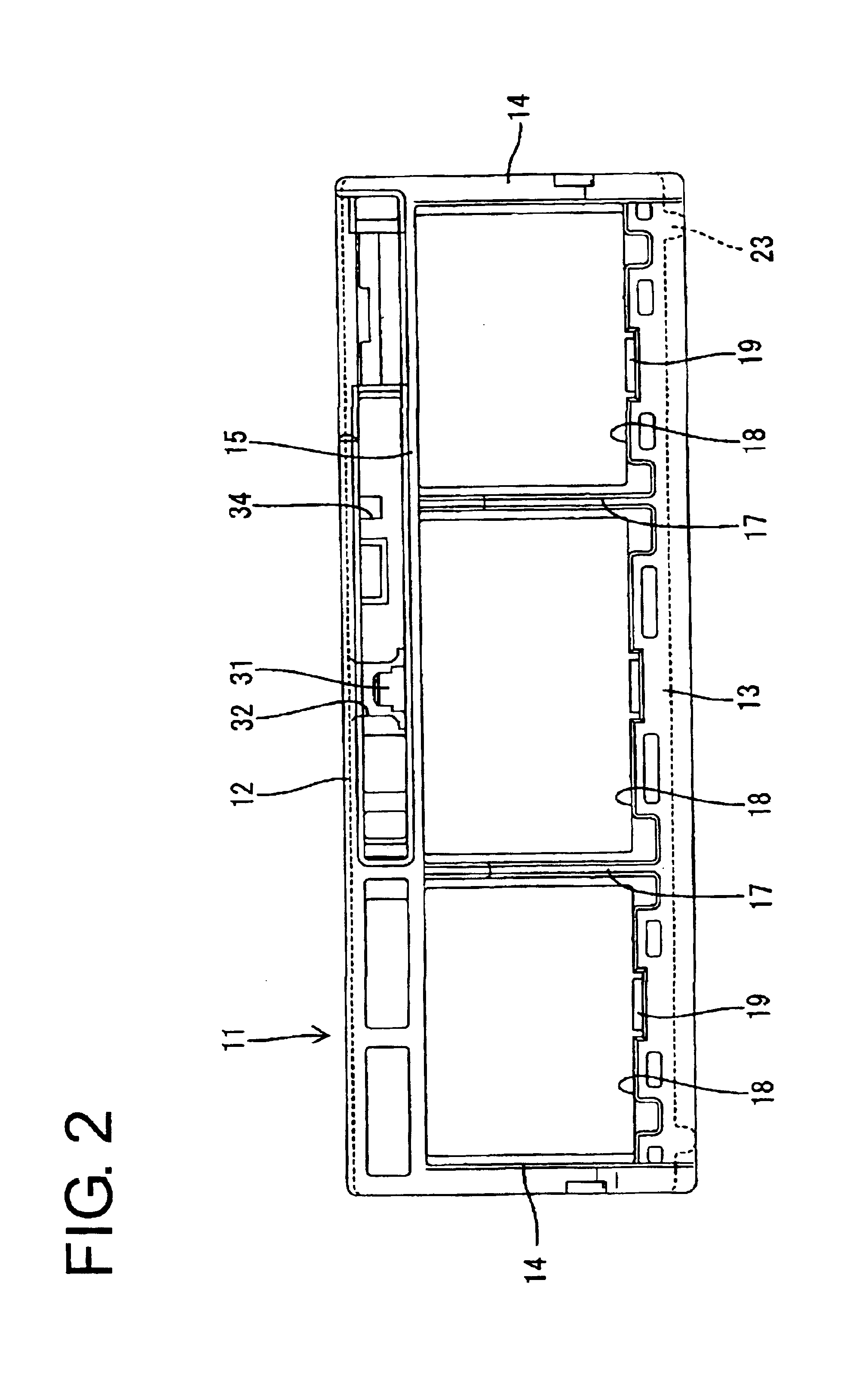
[0052]The female connector 10 is a divided connector and includes a frame-shaped holder 11 that accommodates auxiliary connectors 27. The holder 11 is made e.g. of a synthetic resin and, as shown in FIGS. 1 to 3, is a wide box that is hollow in forward and backward directions. Specifically, the holder 11 has an upper wall 12, a bottom wall 13 and left and right side walls 14. A ceiling wall 15 extends substantially parallel to the upper wall 12 and an accommodating recess 16 is defined between the upper wall 12 and the ceiling wall 15 for accommodating a lever 40. An area...


PUM


Abstract

A female connector (10) has a lever (40) in the form of a single plate. The lever (40) is locked at an initial position by a resilient lock (46) before a connecting operation with a male connector (50). An unlocking rib (55) projects from the ceiling surface of a receptacle (53) of the male housing (50) near one side for canceling the locked state of the resilient lock (46) during the connecting operation. An insertion preventing rib (56) projects from the inner surface of the receptacle (53) at a side opposite the unlocking rib (55), and an escape groove (47) for receiving the insertion preventing rib (56) is formed in the upper surface of the lever (40). Thus, the female connector (10) can be prevented from being inserted in a wrong posture.

Description

BACKGROUND OF THE INVENTION[0001]1. Field of the Invention[0002]The invention relates to a lever-type connector or a circuit board connector.[0003]2. Description of the Related Art[0004]Japanese Unexamined Patent Publication No. H5-182716 and FIG. 10(A) herein disclose connectors that use the cam action of a lever to reduce a connecting force. With reference to FIG. 10(A) a connector of this type has first and second housings 1, 2. The first housing 1 has a wide box-shape and is fit into a wide receptacle 3 of the second housing 2. A lever 4 is mounted in an upper part of the first housing 1 and has a cam groove (not shown). A cam pin 5 is in the center of the ceiling surface of the receptacle 3 of the second housing 2, and an unlocking rib 6 is provided at the left side of the cam pin 5 when viewed from the front. The lever 4 is locked at an initial position by a locking means (not shown) between the lever 4 and the housing 1 before the housings 1, 2 are connected. The housings 1, ...

Claims


Application Information

Patent Timeline
Patent Type & Authority Patents(United States)
IPC IPC(8): H01R13/629
CPCH01R13/62938H01R13/62955H01R12/727H01R13/6295
Inventor SHINOZAKI, TETSUYATAKADA, KIYOKAZUNAKANO, HIROSHI
Owner SUMITOMO WIRING SYST LTD
Why Eureka
Try Eureka