
Joy stick control system for a modified steering system for small boat outboard motors

a technology of steering system and joy stick, which is applied in the direction of propulsive elements, vessel construction, marine propulsion, etc., to achieve the effect of fast steering respons

Inactive Publication Date: 2005-09-13
FELL WILLIAM P +1
View PDF6 Cites 18 Cited by
  • Summary
  • Abstract
  • Description
  • Claims
  • Application Information

AI Technical Summary

Benefits of technology

[0008]The instant invention overcomes this problem by creating a directional nozzle for the jet output that is attached to a control cable system. This cable causes the directional nozzle to turn, which causes the trust of the jet output to turn the boat. Thus, the boat can be steered without having to turn the entire motor. Two different mechanisms are disclosed that enable the steering. The first is a tiller system that operates much like the traditional tiller on an outboard motor. However, unlike those tillers, this tiller operates the directional nozzle and does not turn the entire motor. The second mechanism is a bicycle handlebar system that is placed forward of the motor, much like a traditional wheel. The handlebar system, when combined with the new steering system, produces faster steering response without the effort required to turn the wheel to make large sweeping turns.
[0010]The system has a substantial advantage over standard steering systems. First, is speed of control. The boat turns much faster because the movement of the steering control is minimized. Second, the operation of the boat is optimized because the motor remains stationary, which helps maintain optimum water flow under the boat.

Problems solved by technology

However, unlike those tillers, this tiller operates the directional nozzle and does not turn the entire motor.
First, is speed of control.

Method used


Image

  • Joy stick control system for a modified steering system for small boat outboard motors
  • Joy stick control system for a modified steering system for small boat outboard motors
  • Joy stick control system for a modified steering system for small boat outboard motors

Examples


Embodiment Construction

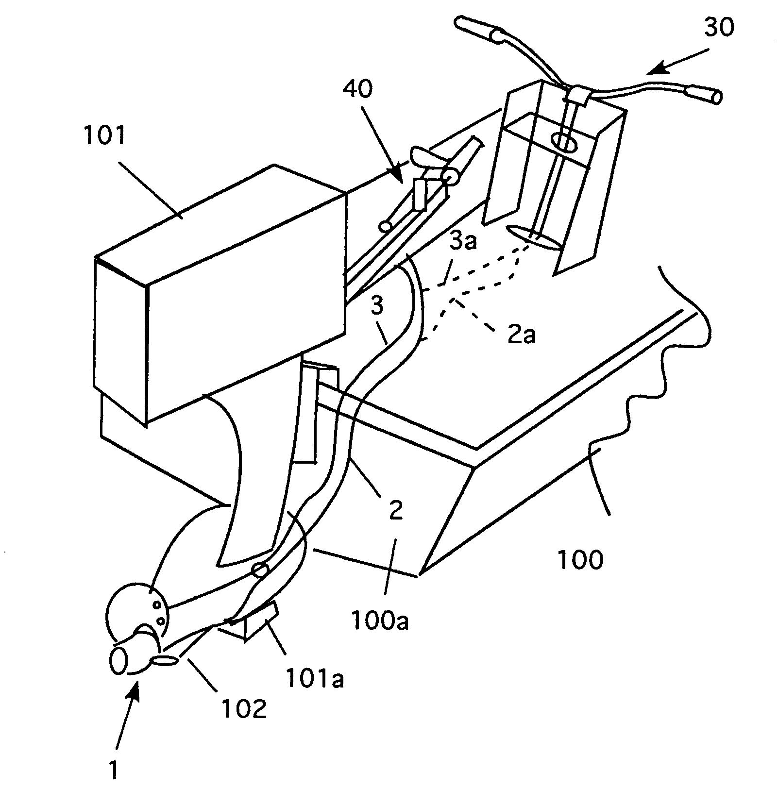
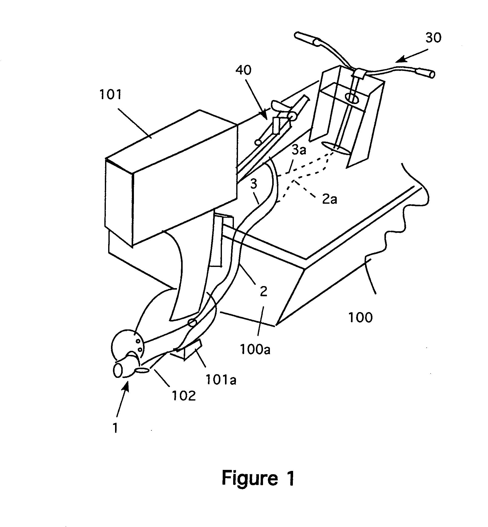
[0029]Referring now to FIG. 1, a detail view of the invention, the jet pump steering (JPS) system is shown. FIG. 1 shows a portion of a boat 100 that has a transom 100a on which an outboard motor 101 is mounted. The motor 101 has a jet pump drive 102 (see FIG. 2) on its lower unit 101a. The figure shows the JPS system 1 mounted to the lower unit 101a of the motor 101. Control cables 2 and 3 are shown running from the JPS system 1 to the control tiller 30. Dashed lines 2a and 3a are shown running to the optional handlebar steering system 40. Both the control tiller and the handlebar steering system are discussed in greater detail below.

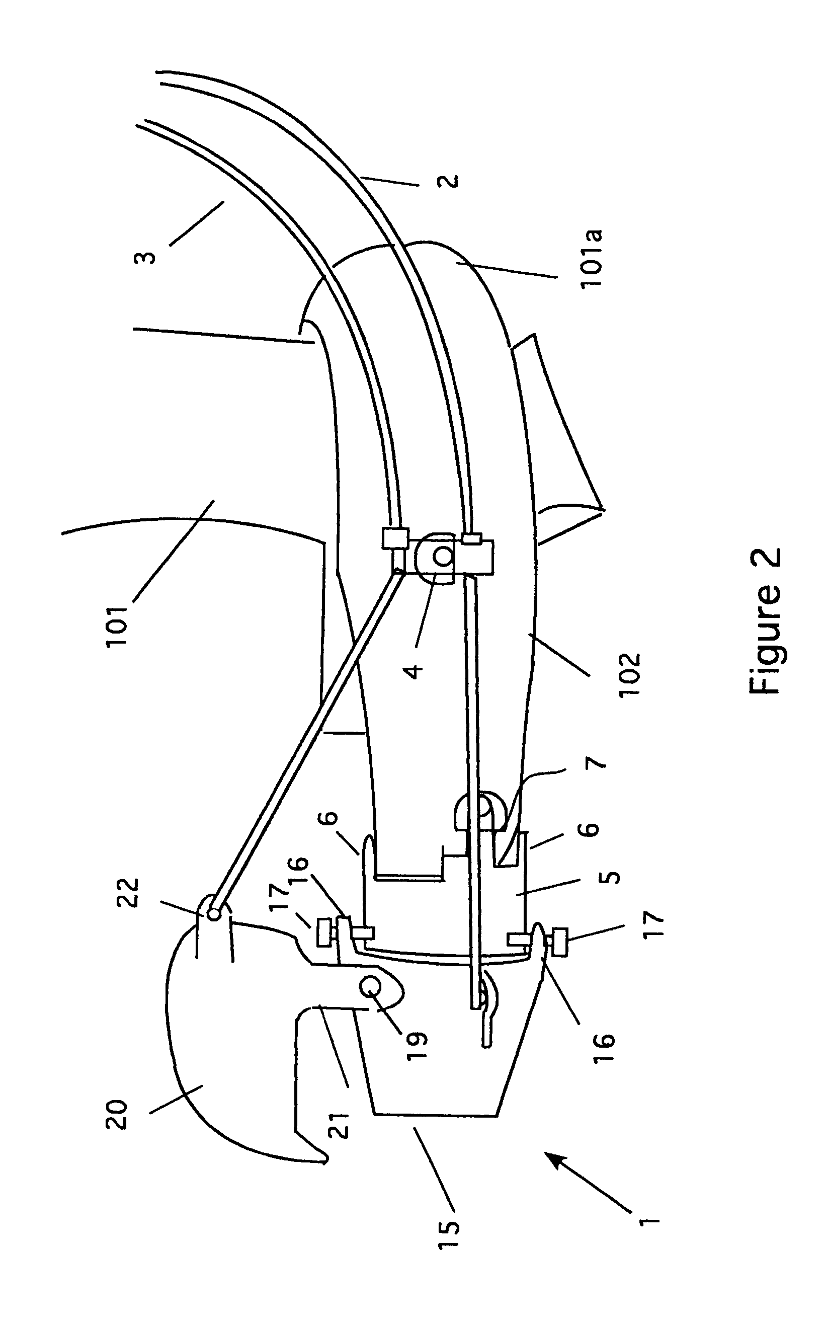
[0030]FIG. 2 is a side detail view of the JPS system 1. Here, the lower unit 101a of the motor 101 is shown. The jet pump output 102 extends out from the back of the lower unit 101a. The JPS has three main parts. First, there is an adaptor ring 5 (see FIG. 4). Next, there is a directional nozzle 15 (see FIG. 5) and then there is a reverse thrust cap 20...


PUM


Abstract

A joystick controller for modified steering system for boats with outboard motors. The system uses a directional nozzle for the jet output that is attached to a control cable system. This cable turns the directional nozzle, which causes the trust of the jet output to turn the boat. Thus, the boat can be steered without having to turn the entire motor. The system also has a reversing cup to change direction. The system uses a joystick that connects to a set of actuators, which in turn, connect to the directional nozzle, reverse cup and throttle. In this way, the joystick can control the movement of the boat in any direction. The joystick can be used with a conventional motor as well.

Description

CROSS REFERENCE TO RELATED APPLICATIONS[0001]This is a continuation in part of application Ser. No. 10 / 696,418, filed on Oct. 29, 2003, now copending.STATEMENT REGARDING FEDERALLY SPONSORED RESEARCH AND DEVELOPMENT[0002]Not ApplicableBACKGROUND OF THE INVENTION[0003]1. Field of the Invention[0004]This invention relates to jet powered steering system for small boat outboard motors and particularly to jet powered steering system for small boats that steer without turning the outboard motor.[0005]2. Description of the Prior Art[0006]Outboard motors have been in use decades. These units have a small engine that is attached to a drive shaft, which in turn, drives a propeller or jet drive. The output of these motors propels the boat forward. To turn the boat, the user must guide the output of the motor to one side of the stern. This is typically accomplished in one of two ways. The first uses a tiller arm that is directly attached to the motor. This system is usually found on smaller moto...

Claims


Application Information

Patent Timeline
CPCB63H21/265B63H20/12B63H21/213B63H2025/024B63H2025/026
Inventor FELL, WILLIAM P.O'HARA, WILLIAM P.
Owner FELL WILLIAM P
Learn More