Dry end surface treatment using ultrasonic transducers

a technology of ultrasonic transducers and end surfaces, applied in the direction of applied substance rearrangement, plant processing, coatings, etc., can solve the problems of weaker ultrasound field, no ultrasound can penetrate into the medium to be treated, and little or no useful ultrasound effect is achieved within the substrate to be treated, etc., to achieve less water to dry up and remove, reduce the viscosity of the coating, and reduce the effect of viscosity

Inactive Publication Date: 2005-09-13
UFO
View PDF2 Cites 3 Cited by
  • Summary
  • Abstract
  • Description
  • Claims
  • Application Information

AI Technical Summary

Benefits of technology

[0010]The method of the present invention provides a solution to the above outline problems. More particularly, the method is for applying a coating on a paper substance. A paper moves over a set of rollers. A coating is applied with a coating applicator that has ultrasonic transducers to vibrate the coating to reduce the viscosity of the coating. A downstream blade has an ultrasonic transducer in operative engagement with the blade. The vibrating blade is applied to the paper for scraping off excessive coating from the paper. The ultrasonic energy of the blade makes it possible to use a coating with a higher dryness so that there is less water to dry up and remove and still get a smooth coating surface.

Problems solved by technology

This means that the greater the speed of flow is, the stronger the ultrasound field will have to be in order to bring the bubbles to violent implosion and collapse.
The ultrasound cannot penetrate through this cushion, and consequently no ultrasound can penetrate into the medium to be treated.
All the cavitation bubbles in this cushion will then stay in the cushion and cause severe cavitation damage to the ultrasound transducer assembly area leading to a necessary exchange of that part of the ultrasound system.
This means that little or no useful ultrasound effect is achieved within the substrate to be treated, and that the ultrasound equipment may be severely damaged.
The above problems also apply to the application of coating to papers.

Method used


Image

  • Dry end surface treatment using ultrasonic transducers
  • Dry end surface treatment using ultrasonic transducers
  • Dry end surface treatment using ultrasonic transducers

Examples


Embodiment Construction

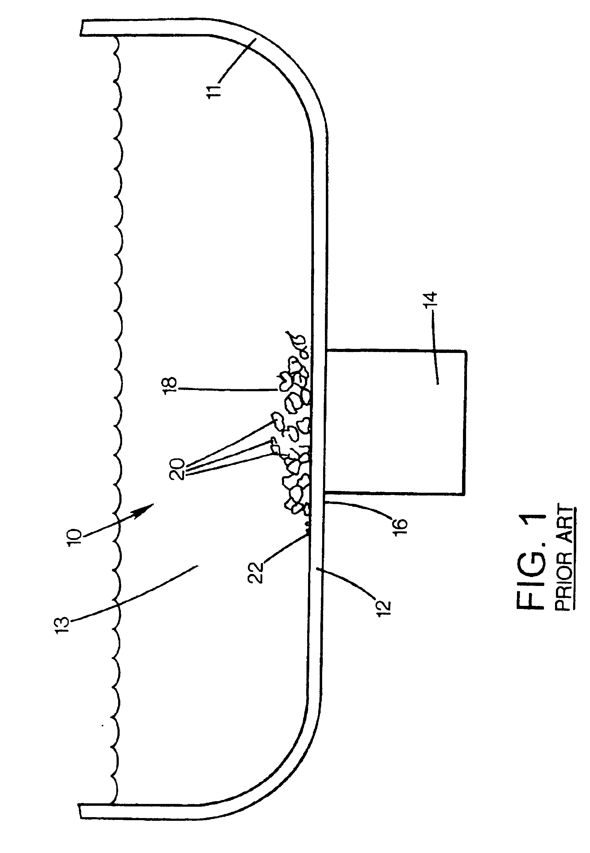
[0028]FIG. 1 is a side view of a prior art transducer system 10 that has a container 11, such as a stainless reactor, with a wall 12 for containing a liquid 13. A transducer 14 is attached to an outside 16 of the wall 12. When the transducer 14 is activated, a pillow 18 of cavitation bubbles 20 are formed on an inside 22 of the wall 12 due to the fracture zone in the liquid 13 that may be a result of fracture impressions on the inside 22 of the wall 12. The bubbles may be held to the inside wall due to the surface tension of the liquid 13. The bubbles 20 are good insulators and prevent the effective transmission of the ultrasonic energy into the liquid 13. The under-pressure pulses of the ultrasonic energy transmitted by the transducer 14 create the cavitation bubbles. In this way, the pressure inside the bubbles is very low.

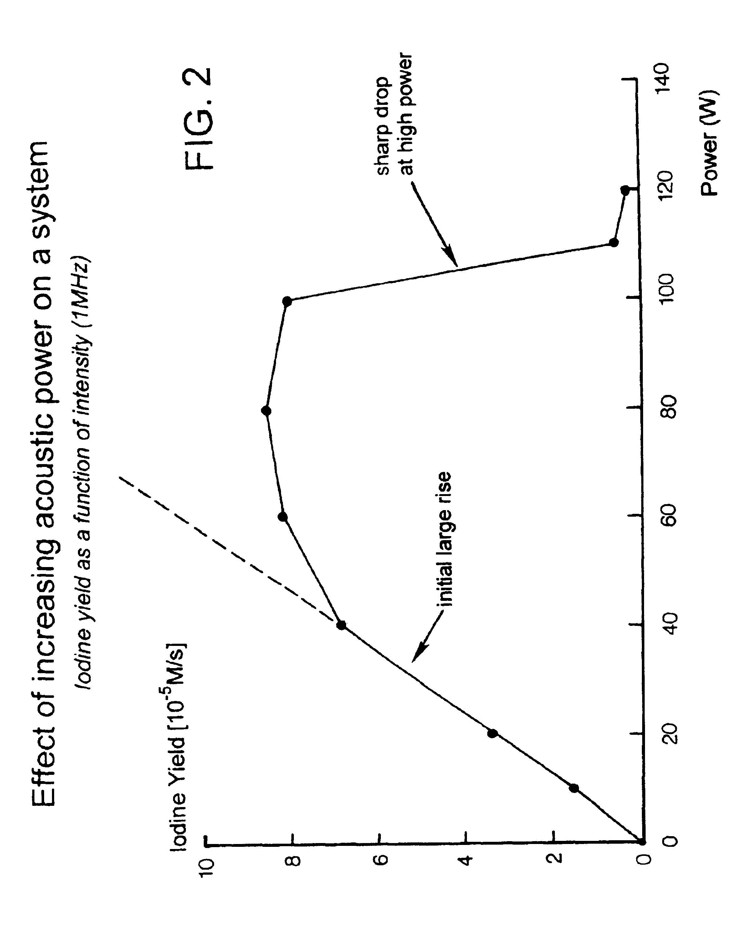
[0029]FIG. 2 is a graphical illustration that shows the iodine yield is affected by increased acoustic power on the system 10. The more power is applied, the th...


PUM

PropertyMeasurementUnit
pressureaaaaaaaaaa
frequencyaaaaaaaaaa
widthaaaaaaaaaa

Abstract

The method is for applying a coating on a paper substance. A paper moves over a set of rollers. A coating is applied with a coating applicator that has ultrasonic transducers to vibrate the coating to reduce the viscosity of the coating. A downstream blade has an ultrasonic transducer in operative engagement with the blade. The vibrating blade is applied to the paper for scraping off excessive coating from the paper.

Description

PRIOR APPLICATION[0001]This is a continuation-in-part application of U.S. patent application Ser. No. 10 / 451,962, filed 27 Jun. 2003 that claims priority from PCT application No. PCT / SE02 / 02195, filed 28 Nov. 2002, that claims priority from U.S. provisional patent application Ser. No. 60 / 339,380, filed 11 Dec. 2001.TECHNICAL FIELD[0002]The present invention is a method for a paper machine dry end or off line coater paper surface treatment using ultrasonic transducers.BACKGROUND AND SUMMARY OF INVENTION[0003]Ultrasonic energy has been applied to liquids in the past. Sufficiently intense ultrasonic energy applied to a liquid, such as water, produces cavitation that can induce changes in the physiochemical characteristics of the liquid. The subject of sonochemistry, which deals with phenomena of that sort, has grown very much during recent years.[0004]The published material is sonochemistry and related subjects all pertains to batch processes, that is, the liquid solution or dispersion...

Claims


Application Information

Patent Timeline
Patent Type & Authority Patents(United States)
IPC IPC(8): B01J19/10B01J19/00C02F1/36C02F1/34C02F11/04C02F1/52B05C1/14B05C3/18B05C11/04D21H25/10
CPCB01J19/008B01J19/10B05C1/14B05C11/04C02F1/36C02F11/04D21H25/10B01J2219/0877B01J2219/089B05C3/18C02F1/52C02F2103/28
Inventor DAHLBERG, HAKAN
Owner UFO
Why Eureka
Try Eureka