
Battery system thermal management

a power supply system and thermal management technology, applied in the field of battery power supply, can solve the problems of prior art generally failing to provide power supply system thermal management and operation, and achieve the effect of improving power supply system and method of operation

Inactive Publication Date: 2005-09-13
ILLINOIS INSTITUTE OF TECHNOLOGY
View PDF62 Cites 66 Cited by
  • Summary
  • Abstract
  • Description
  • Claims
  • Application Information

AI Technical Summary

Benefits of technology

[0013]A general object of the invention is to provide a

Problems solved by technology

The prior art generally fails to provide a power supply system and method of operation which provides or results in thermal management which is either or both as effective and efficient as may be desired.
Further, the prior art generally fails to provide power supply system thermal management and operation such as may more conveniently or effectively permit the use of larger-sized battery power supplies such as contemplated or envisioned for certain applications, such as to power electric vehicles, for example.

Method used


Image

  • Battery system thermal management
  • Battery system thermal management
  • Battery system thermal management

Examples


examples

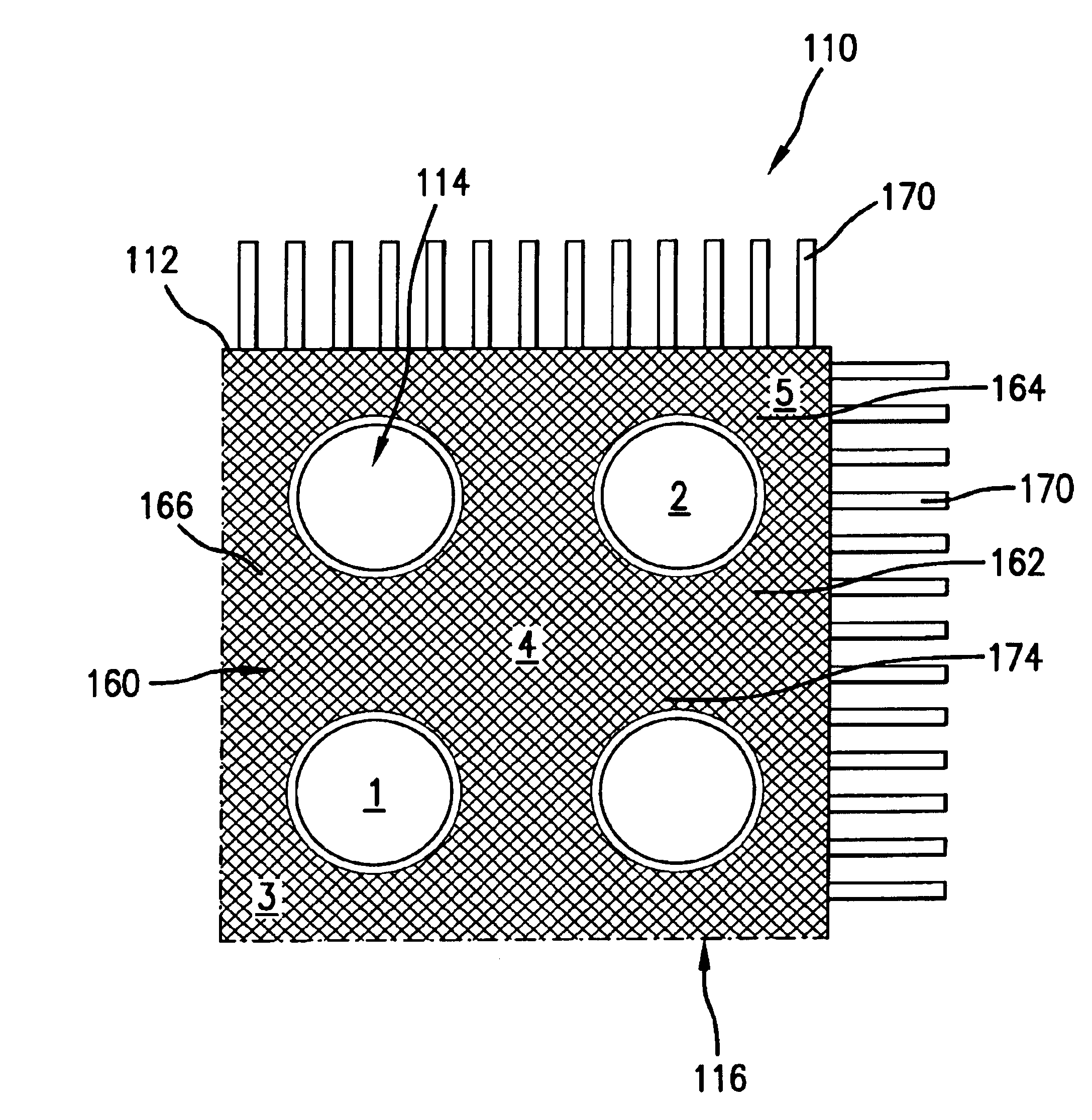
[0078]For purposes of these simulation examples, battery module quadrants corresponding to those shown and described above relative to FIGS. 11, 12 and 13 were evaluated at four selected cooling rates, e.g., h=0, 10, 50 and 100 W·m−1·K−1, respectively, with temperature measurements at the locations designated “1”, “2”, “3”, “4” and “5”, as shown on FIGS. 11, 12 and 13, respectively. As shown, the point or location designated “1” is a cell present on the inner side or region of the module. The point or location designated “2” is a cell present on the outer side or region of the module. The point or location designated “4” correspond to the center or central region of the respective module quadrant.

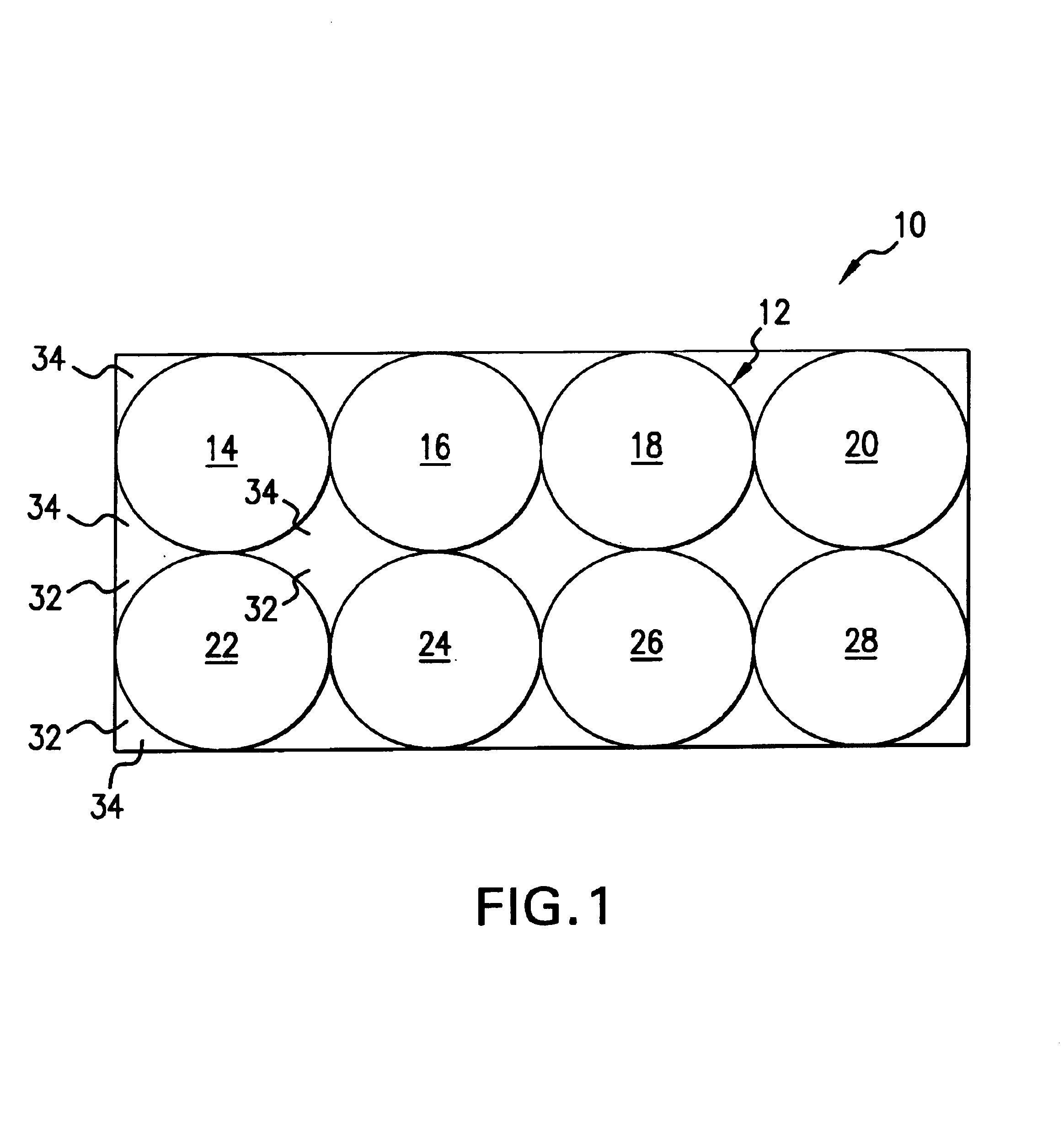
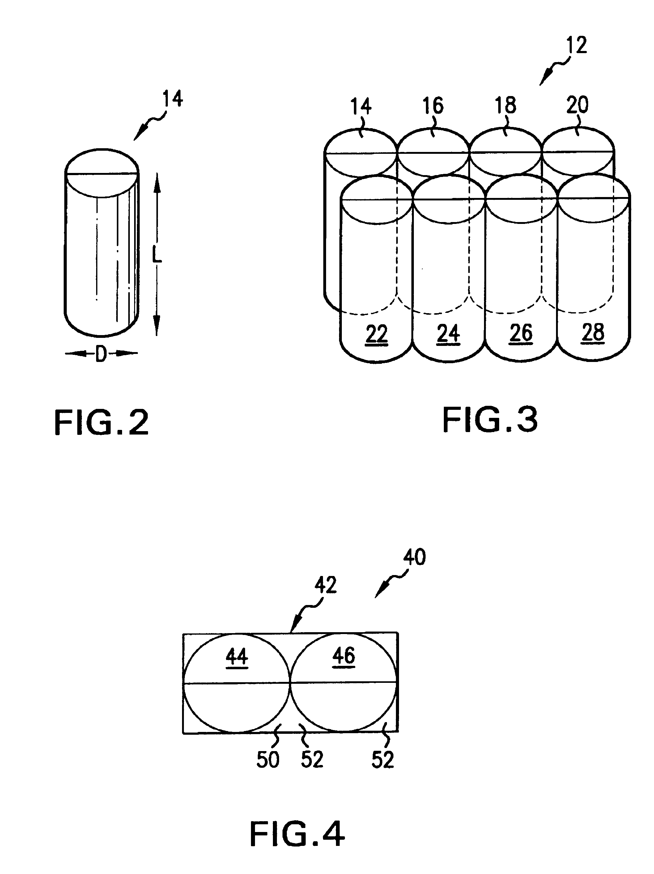
[0079]In each case:[0080]a. each of the four electrochemical cells were Li-ion cells each having a capacity of 1.8 Ah with a diameter (corresponding to D shown in FIG. 2) of 18 mm and a height or length (corresponding to L shown in FIG. 2) of 65 mm. The four cells in each of the module quad...


PUM


Abstract

Power supply systems and associated methods of operation are provided based on the incorporation of a supply of phase change material in thermal contact with at least one cell element capable of a heat-generating charge or discharge of power. Also disclosed, such as for increased or improved heat transfer and dissipation, is battery module incorporation of a heat-conductive containment lattice member such as having a plurality of openings wherein at least a portion of the supply of the phase change material can be disposed as well as the inclusion of a plurality of module housing-protruding heat transfer fins.

Description

CROSS REFERENCE TO RELATED APPLICATION[0001]This application is a continuation-in-part of U.S. application, Ser. No. 09 / 515,268, filed on 29 Feb. 2000. The co-pending parent application is hereby incorporated by reference herein in its entirety and is made a part hereof, including but not limited to those portions which specifically appear hereinafter.BACKGROUND OF THE INVENTION[0002]This invention relates generally to battery power supply and, more particularly, to thermal management in such battery power supply systems. The word “battery” here is meant to include various forms of electrochemical power generation which have in common that chemical energy, in the form of one or more chemical reactants stored in a confined space, react with each other or with an external reactant in an electrochemical reaction, so as to produce electric power when desired.[0003]Various uses of battery power supplies have been well established. For example, the packaging together of a plurality of cel...

Claims


Application Information

Patent Timeline
IPC IPC(8): H01M10/42H01M2/10H01M10/50H01M8/02H01M6/00H01M10/36H01M6/50H01M10/40H01M6/42H01M10/052
CPCH01M2/1094H01M8/04007H01M8/04067H01M10/4207H01M10/5004H01M10/5006H01M10/5008H01M10/5012H01M10/5016H01M10/503H01M10/5036H01M10/5046H01M10/5055H01M10/5089H01M6/42H01M8/04052H01M10/052H01M10/5067H01M10/5075H01M2200/10Y02E60/50Y02T10/7011H01M10/613H01M10/615H01M10/617H01M10/623H01M10/625H01M10/643H01M10/651H01M10/6551H01M10/6555H01M10/6563H01M10/6567H01M10/659H01M50/24Y02E60/10
Inventor AL-HALLAJ, SAIDSELMAN, JAN ROBERT
Owner ILLINOIS INSTITUTE OF TECHNOLOGY
Features
  • Generate Ideas
  • Intellectual Property
  • Life Sciences
  • Materials
  • Tech Scout
  • Unparalleled Data Quality
  • Higher Quality Content
  • 60% Fewer Hallucinations
Learn More