Clamp for a vibration damper and method of installing same

a technology of vibration damper and clamp, which is applied in the direction of electric cable installation, overhead installation, suspension arrangement, etc., can solve the problems of inability to use the method of vibration damper installation during new construction on existing construction, failure of conductor strands and/or conductor supports in fatigue, and inability to de-energize conductors even for a short time. , to achieve the effect of rapid installation

Inactive Publication Date: 2005-09-13
ARIZONA PUBLIC SERVICE
View PDF19 Cites 12 Cited by
  • Summary
  • Abstract
  • Description
  • Claims
  • Application Information

AI Technical Summary

Benefits of technology

[0014]Accordingly, it is an advantage of the present invention that a clamp for a vibration damper and a method for installing the vibration damper is provided.
[0015]Another advantage of the present invention is that a clamp is provided that is resistant to rotation during installation.
[0016]It is another advantage of the present invention that a clamp for a vibration damper is provided that enables a single lineman to install the vibration damper.
[0017]Yet another advantage of the present invention is that the clamp enables the vibration damper to be rapidly installed on an energized conductor using a single live line tool.
[0018]The above and other advantages of the present invention are carried out in one form in a vibration damper by a clamp for attachment to a suspended conductor, the vibration damper including a damping structure. The clamp includes a base having a housing for attachment to the damping structure and a first clamp member extending from the housing. The first clamp member has a first extension section and a second extension section. A second clamp member is positioned between the first and second extension sections. The first and second clamp members cooperate to provide a passageway for the suspended conductor. A fastener secures the second clamp member to the first clamp member, and the first and second extension sections continuously abut the second c

Problems solved by technology

Even though the amplitude or intensity of aeolian vibration is small (rarely more than the diameter of the conductor when measured from peak to peak), the effect of such a vibration is to cause the conductor strands and/or conductor supports to fail in fatigue.
The method of installation of vibration dampers utilized during new construction often cannot be employed on existing construction without taking a planned power outage.
Obviously, de-energizing conductors even for a short duration is an unsatisfactory situation.
Power outages, planned or otherwise, are inconvenient, disrupting the operation of electrically-powered heating and air c

Method used


Image

  • Clamp for a vibration damper and method of installing same
  • Clamp for a vibration damper and method of installing same
  • Clamp for a vibration damper and method of installing same

Examples


Embodiment Construction

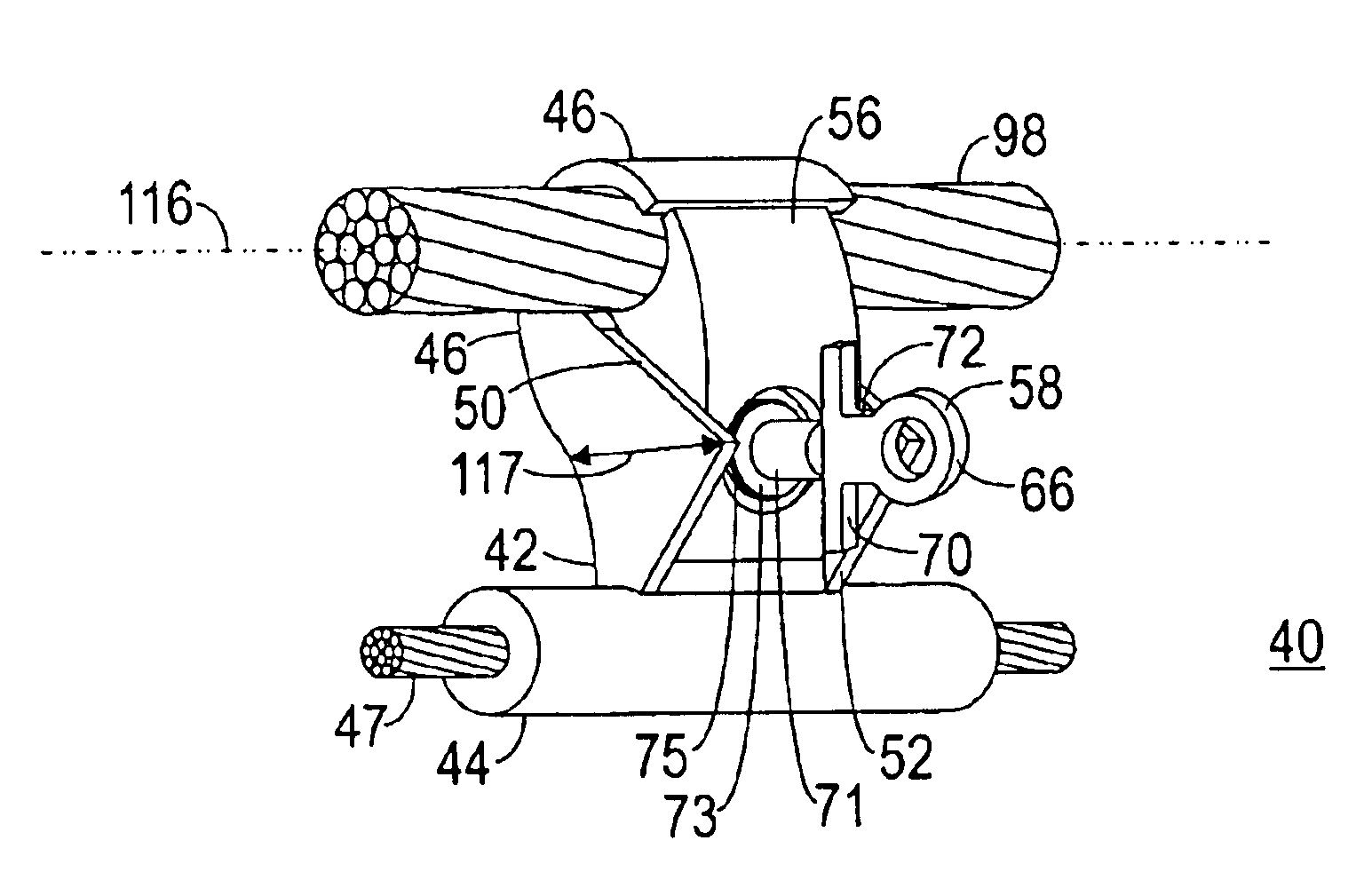
[0028]The present invention entails a clamp for a vibration damper and a method for installing the vibration damper that can be performed by a single lineman utilizing a conventional shotgun stick. The vibration damper can be advantageously installed on an energized electrical conductor on existing construction.

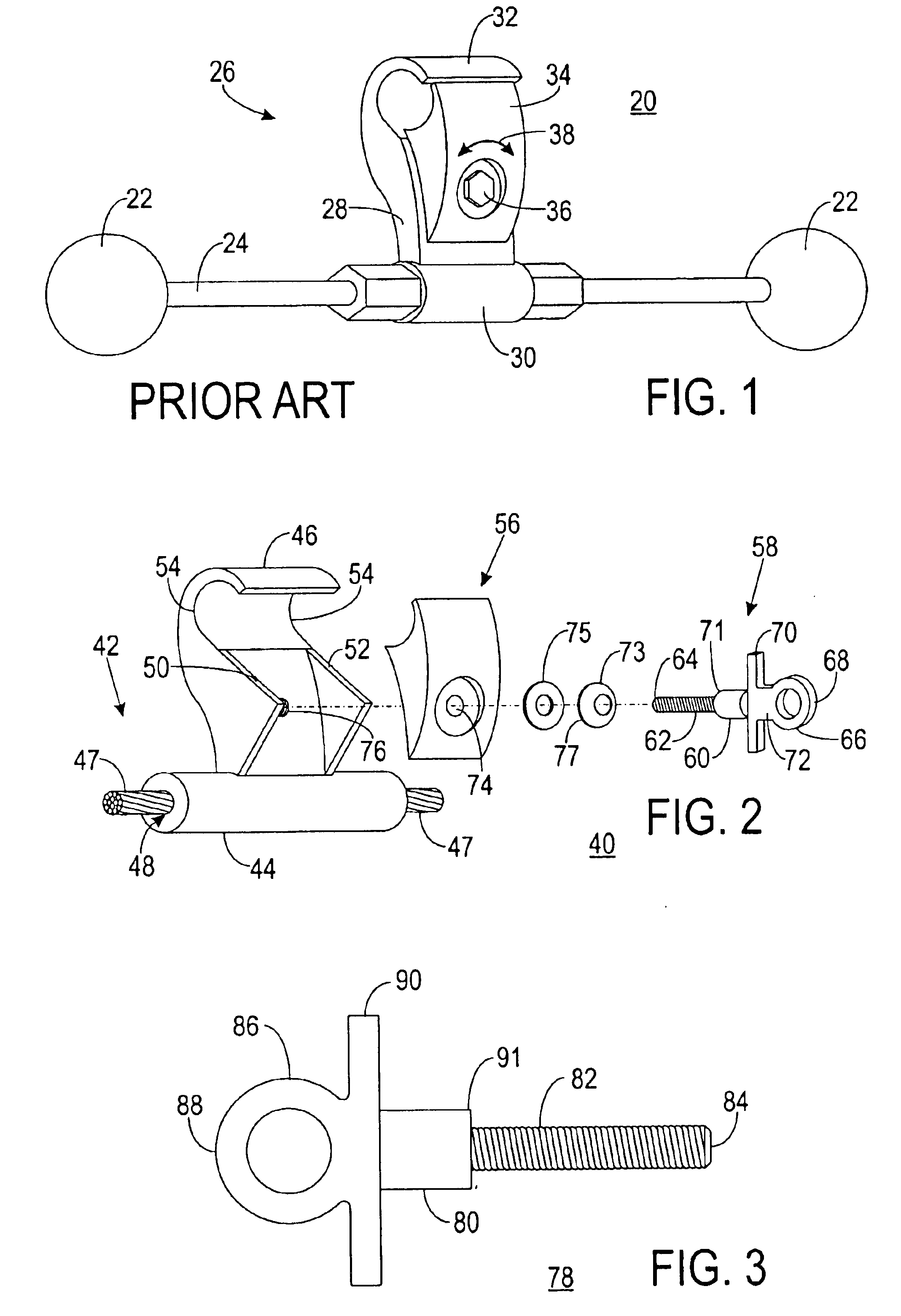
[0029]FIG. 2 shows an exploded perspective view of a clamp 40 for a vibration damper in accordance with a preferred embodiment of the present invention. Clamp 40 includes a base 42 having a housing 44 and a first clamp member 46 extending therefrom. Housing 44 is adapted for attachment to a damping structure 47. For example, housing 44 includes a bore 48 through which a portion of damping structure 47 can be directed. First clamp member 46 includes a first extension section 50 and a second extension section 52. First and second extension sections 50 and 52, respectively, project from outer edges 54 of first clamp member 46.

[0030]In an exemplary embodiment, damping structure 4...


PUM


Abstract

A clamp (40) for attaching a vibration damper to an energized suspended conductor (98) includes a base (42) having a first clamp member (46) with first and second extension sections (50, 52). The clamp (40) further includes a second clamp member (56) positioned between the extension sections (50, 52), and an eyebolt (58) for securing the second clamp member (56), to the first clamp member (46). The extension sections (50, 52) continuously abut the second clamp member (56) to prevent its rotation about the eyebolt (58). During installation, the eyebolt (58) is captured by a hook member (92) of shotgun stick (94) and a single lineman secures the vibration damper to the conductor (98).

Description

RELATED INVENTION[0001]The present invention is a continuation of “Clamp For A Vibration Damper And Method Of Installing Same,” Ser. No. 10 / 356,086, filed 30 Jan. 2003, now U.S. Pat. No. 6,774,303, issued 10 Aug. 2004, which is incorporated herein by reference.TECHNICAL FIELD OF THE INVENTION[0002]The present invention relates to the field of electrical conductor cables. More specifically, the present invention relates to vibration dampers for limiting wind-induced vibration of the conductor cables.BACKGROUND OF THE INVENTION[0003]Electrical conductor cables suspended overhead from poles and / or towers are subject to a wind induced vibration identified as aeolian vibration. A typical overhead conductor for high voltage transmission of electrical power is comprised of a multi-strand conductor. Even though the amplitude or intensity of aeolian vibration is small (rarely more than the diameter of the conductor when measured from peak to peak), the effect of such a vibration is to cause ...

Claims


Application Information

Patent Timeline
IPC IPC(8): H02G7/00H02G7/14
CPCH02G7/14
Inventor BRITTAIN, CARL C.ORTH, MARK E.WILCOXON, WAYNE D.
Owner ARIZONA PUBLIC SERVICE
Why Eureka
Try Eureka