Variable fixed multipliers using memory blocks

a memory block and variable fixed technology, applied in the field of programmable logic devices, can solve the problems of significant pld resources, inconvenient re-program, and reduced the number of multipliers that can be implemented

Inactive Publication Date: 2005-09-13
ALTERA CORP
View PDF6 Cites 389 Cited by
  • Summary
  • Abstract
  • Description
  • Claims
  • Application Information

AI Technical Summary

Problems solved by technology

One problem with the example multiplier implementation shown in FIG. 1 is that it consumes significant PLD resources in that numerous LUTs 24 are used to implement a multiplier.
Unfortunately, the resources used by each individual multiplier can reduce the number of multipliers that can be implemented in any given PLD chip.
Another problem with prior multipliers implemented in a PLD is that they sometimes have been inconvenient to re-program, especially on-the-fly.

Method used


Image

  • Variable fixed multipliers using memory blocks
  • Variable fixed multipliers using memory blocks
  • Variable fixed multipliers using memory blocks

Examples


Embodiment Construction

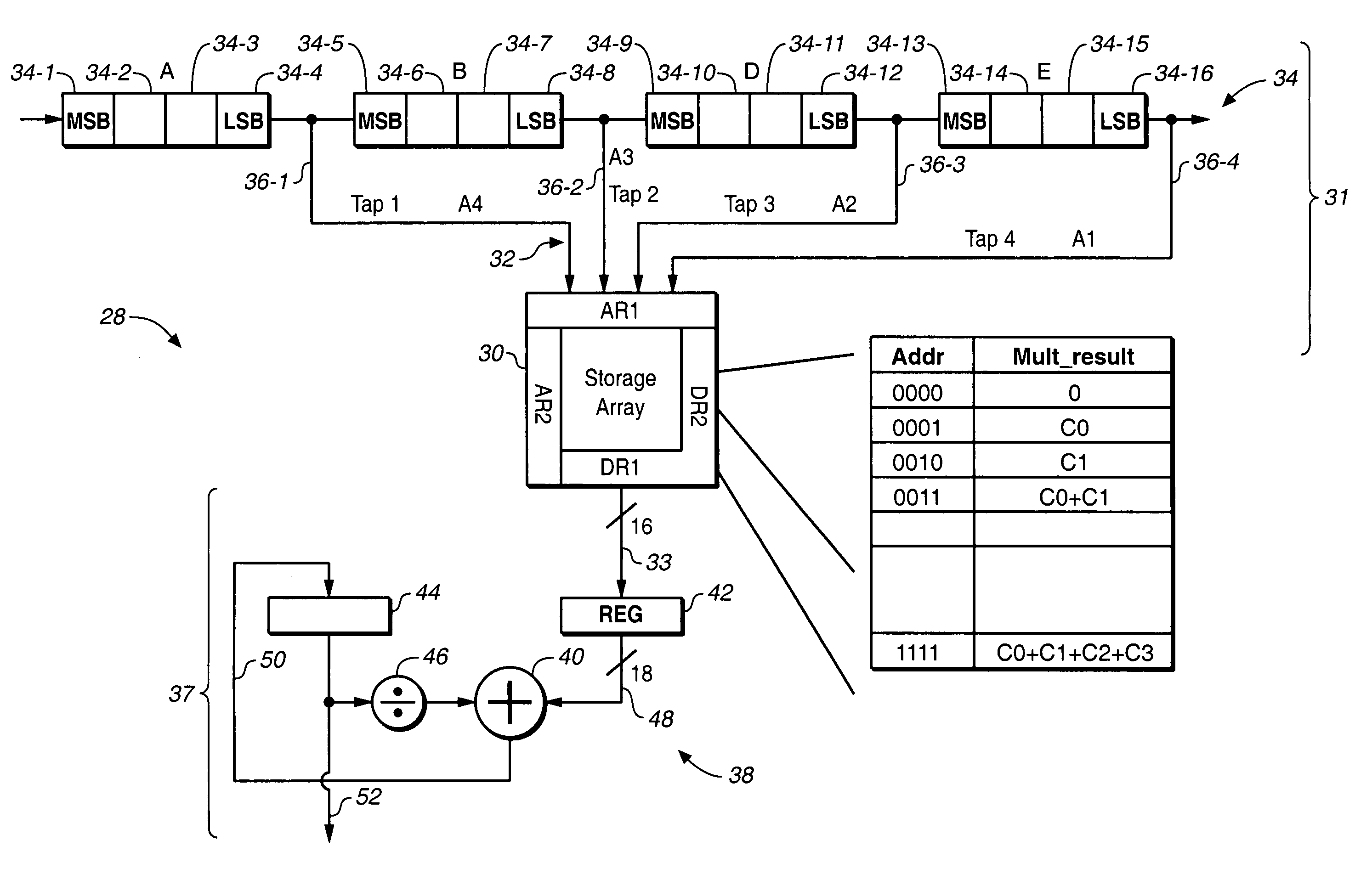
[0030]In one aspect, the present invention provides improvements in the implementation of arithmetic operations, particularly multiplication operations in PLDs having RAM blocks. In a different aspect, the present invention provides improvements in re-programming multipliers in PLDs having RAM blocks. The following description is presented to enable any person skilled in the art to make and use the invention. The embodiments of the invention are described in the context of particular applications and their requirements. These descriptions of specific applications are provided only as examples. Various modifications to the preferred embodiments will be readily apparent to those skilled in the art, and the generic principles defined herein may be applied to other embodiments and applications without departing from the spirit and scope of the invention. Thus, the present invention is not intended to be limited to the embodiments shown, but is to be accorded the widest scope consistent ...


PUM


Abstract

A programmable logic device includes at least one RAM block generating a first multi-bit calculation result which may, but does not necessarily, involve a multiplication of two operands. A shift operation is driven by a second multi-bit calculation result shifts the second multi-bit calculation result by at least one bit to generate a shifted second multi-bit calculation result. A multi-bit adder coupled to the at least one RAM block adds the shifted second multi-bit calculation result to the first multi-bit calculation result.

Description

PRIORITY INFORMATION[0001]The present application is a continuation-in-part of commonly owned U.S. patent application Ser. No. 10 / 326,652 for Programmable Logic Device with Soft Multiplier filed Dec. 20, 2002 is now a U.S. Pat. No. 6,888,372.BACKGROUND OF THE INVENTION[0002]1. Field of the Invention[0003]This invention relates to programmable logic devices (PLDs), and more particularly to implementing multipliers in PLD RAM blocks.[0004]2. Description of the Related Art[0005]A PLD is a digital, user-configurable integrated circuit used to implement a custom logic function. For the purposes of this description, the term PLD encompasses any digital logic circuit configured by an end-user, and includes a programmable array logic array (“PLA”), a field programmable gate array (“FPGA”), and an erasable complex PLD. The basic building block of a PLD is a logic element (“LE”). A LE is capable of performing limited logic functions on a number of input variables. Conventional PLDs combine to...

Claims


Application Information

Patent Timeline
Patent Type & Authority Patents(United States)
IPC IPC(8): G06F7/42G06F7/40H03K19/177G06F7/523
CPCG06F7/523G06F2207/4802
Inventor HAZANCHUK, ASHERESPOSITO, BENJAMIN
Owner ALTERA CORP
Why Eureka
Try Eureka