
Printed circuit board dipole antenna structure with impedance matching trace

a dipole antenna and circuit board technology, applied in the direction of radiating element structural forms, resonance antennas, printed electric components, etc., can solve the problems of increasing the size of the compartment needed to house the two separate components, increasing the cost of producing the combination of antenna and driving circuit, and many limitations

Active Publication Date: 2005-09-13
SENSUS SPECTRUM LLC
View PDF22 Cites 64 Cited by
  • Summary
  • Abstract
  • Description
  • Claims
  • Application Information

AI Technical Summary

Benefits of technology

[0014]Each antenna trace includes a radiating strip extending from the connection strip. The combined length of the two radiating strips is less than one-half the wavelength of the desired frequency that the antenna structure radiates and receives.

Problems solved by technology

The separate antenna device increases the cost to produce the combination of the antenna and driving circuit while also increasing the size of the compartment needed to house the two separate components.
Micro strip patch antennas, however, have many limitations, including the ability to radiate only above the ground plane.
Further, because the micro strip patch antenna has a resonant cavity that greatly depends upon the thickness of the dielectric material utilized, tuning such an antenna is difficult.

Method used


Image

  • Printed circuit board dipole antenna structure with impedance matching trace
  • Printed circuit board dipole antenna structure with impedance matching trace
  • Printed circuit board dipole antenna structure with impedance matching trace

Examples


Embodiment Construction

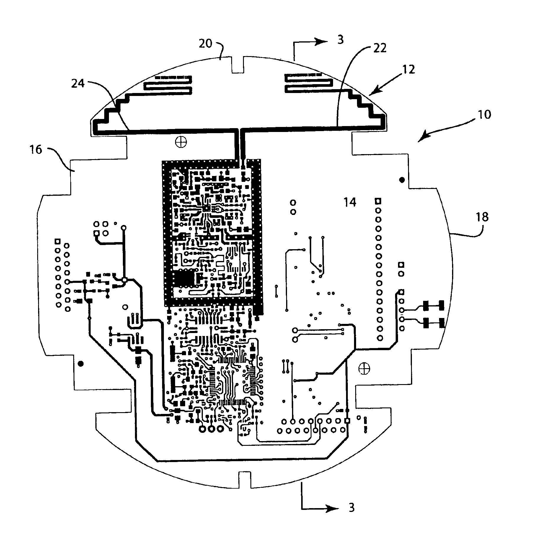
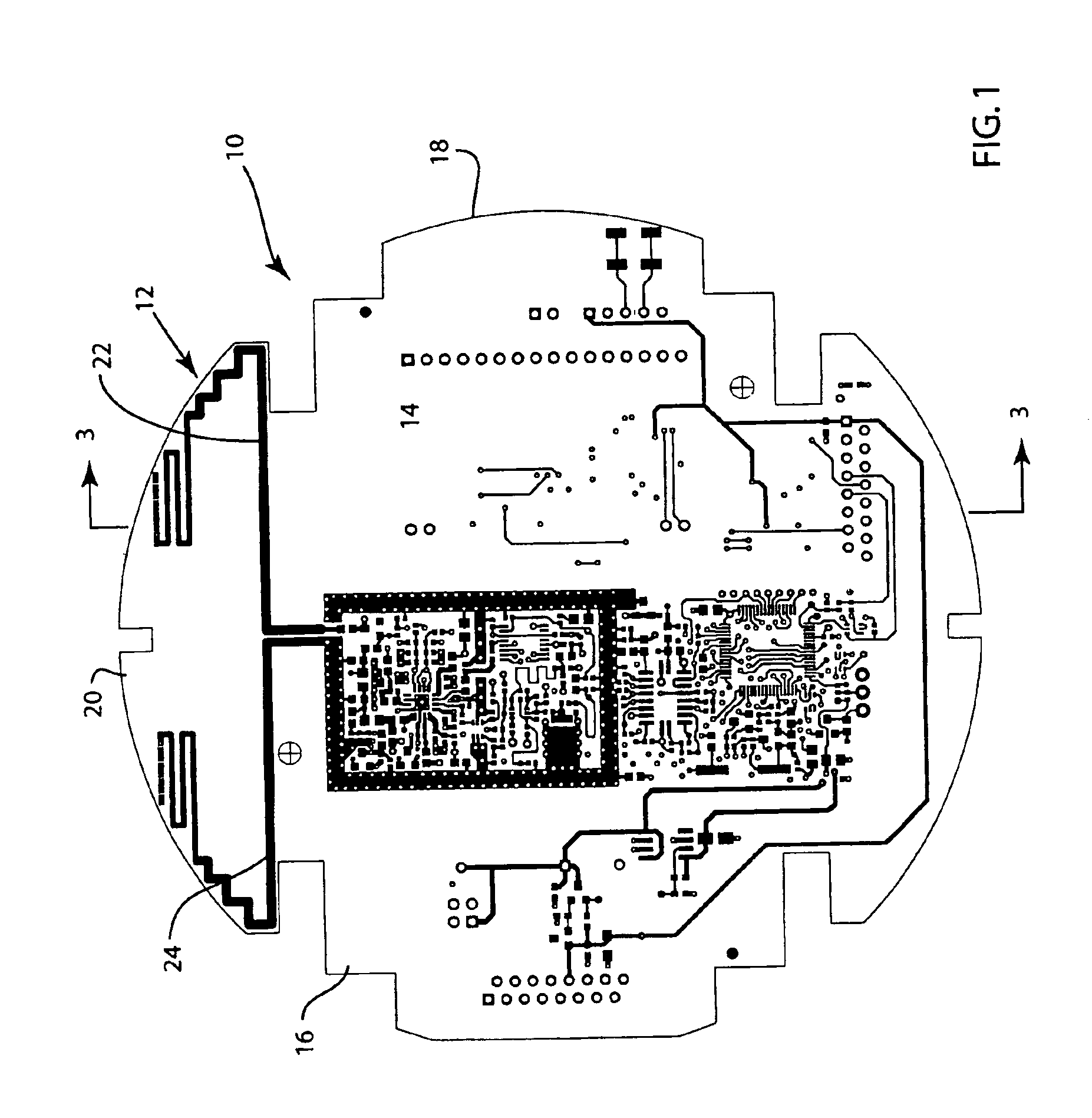
[0028]Referring first to FIG. 1, thereshown is a printed circuit board 10 including both a printed circuit board dipole antenna structure 12 and an antenna driving circuit 14. The antenna driving circuit 14 includes various electronic components for driving and receiving signals from the printed dipole antenna structure 12 of the present invention. The antenna driving circuit 14 both applies and receives radio frequency energy from the printed dipole antenna 12. The antenna driving circuit 14 is mounted to the first, front surface of the circuit board 16 in a known manner, such as by automated surface mount technology techniques. The antenna driving circuit 14 is a conventional configuration and is well known to those skilled in the art. Many different configurations for the antenna driving circuit 14 are contemplated as being within the scope of the present invention. The specific configuration of the antenna driving circuit 14 is not shown, since the specific configuration of the ...


PUM


Abstract

A printed circuit board antenna structure for the transmission of radio frequency energy. The printed circuit board antenna of the present invention includes a circuit board subassembly having a component mounting section and an antenna section. The antenna section of the circuit board includes a pair of antenna traces that function as two sides of a dipole antenna. Each antenna trace includes a radiating strip where the combination of the pair of radiating strips has a length less than one-half the wavelength of the desired radiation being transmitted. Each antenna trace includes an impedance matching strip having a serpentine structure and coupled to the radiating strip. The impedance matching strip matches the desired impedance for the antenna driving circuit.

Description

CROSS-REFERENCE TO RELATED APPLICATIONS[0001]The present application is based on and claims priority to U.S. Provisional Patent Application No. 60 / 444,086 filed on Jan. 31, 2003.FIELD OF THE INVENTION[0002]The present invention generally relates to the field of antennas for transmitting radio frequency signals. More particularly, the present invention relates to a printed antenna comprised of thin layers of electrically conductive material that are bonded onto a thin, planar dielectric material such as a printed circuit board (PCB) that also serves as a platform for an antenna driving circuit.BACKGROUND OF THE INVENTION[0003]Presently, the desire for antennas for transmitting radio frequency signals from a small, compact location to an external receiver has grown significantly. For example, antennas for transmitting radio frequency signals from a recording or monitoring device, such as a thermostat, water meter, gas meter, electric meter or any similar type of device to a remote loc...

Claims


Application Information

Patent Timeline
Patent Type & Authority Patents(United States)
IPC IPC(8): H01Q23/00H01Q1/38H01Q9/04H01Q9/28H05K1/16
CPCH01Q1/38H01Q9/285H01Q23/00H01Q1/2233H05K1/16H01Q9/28
Inventor PAUN, CRISTIAN
Owner SENSUS SPECTRUM LLC
Features
  • Generate Ideas
  • Intellectual Property
  • Life Sciences
  • Materials
  • Tech Scout
  • Unparalleled Data Quality
  • Higher Quality Content
  • 60% Fewer Hallucinations
Learn More