

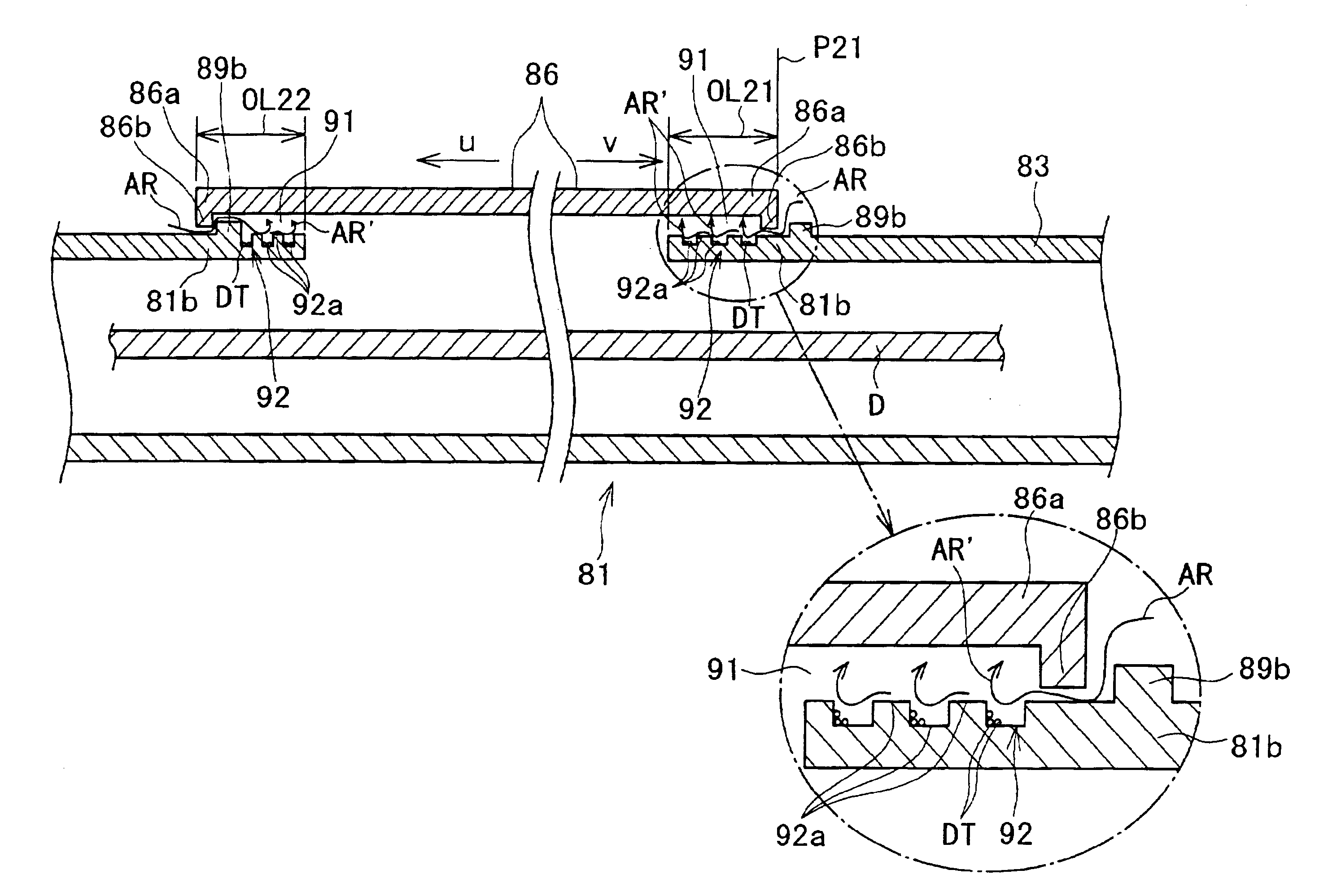
Disc cartridge with shutter overlapping gap having labyrinth shaped portion spaced to have a recessed dust deposition portion
a disc cartridge and shutter technology, applied in the field of cartridges, can solve the problems of difficult to correct, high density recording disc cartridges, above-described dustproof structures, disadvantages, etc., and achieve the effect of preventing the permeation of air containing dus
- Summary
- Abstract
- Description
- Claims
- Application Information
AI Technical Summary
Benefits of technology
Problems solved by technology
Method used
Image

Examples
Embodiment Construction
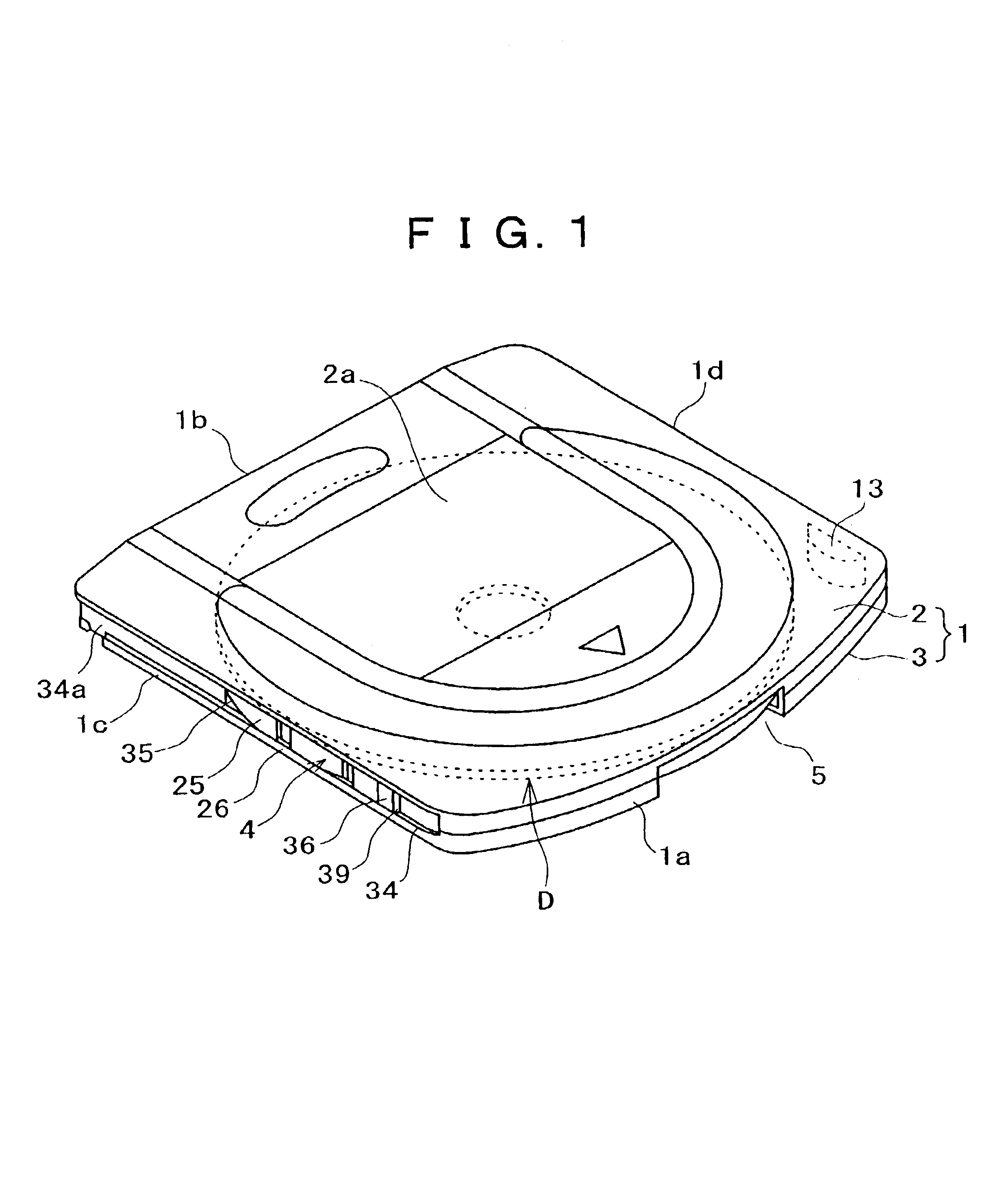
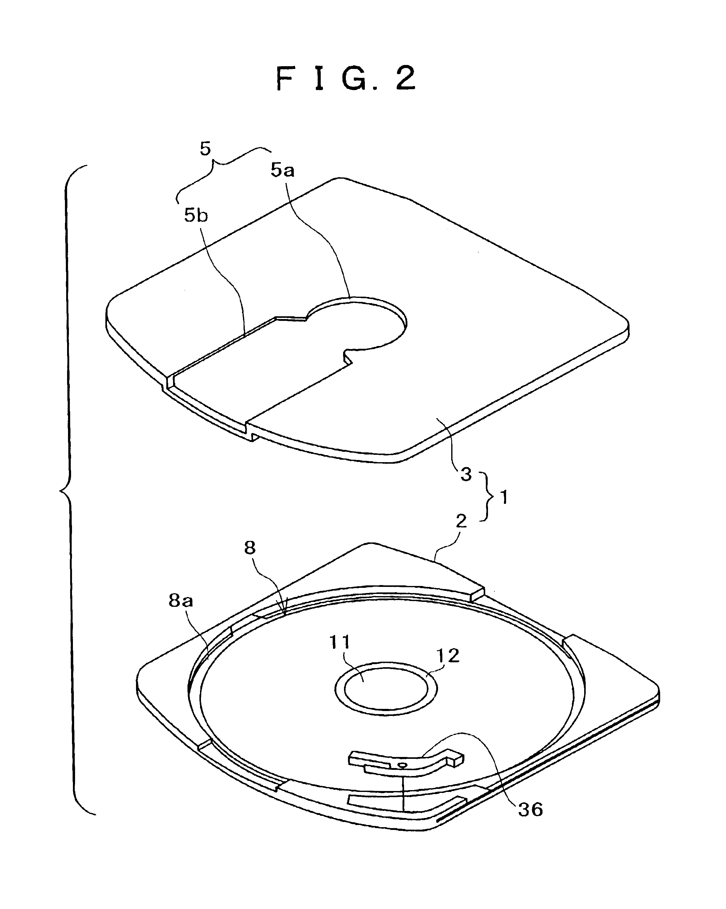
[0079]Hereinafter, preferred embodiments of disk cartridges to which the present invention is applied will be described with reference to the drawings. The description of the embodiments will be made in the following order:[0080](1) Description of Outline of Disk Cartridge Using Inner Rotor (FIGS. 1 to 13)[0081](2) Description of First Dustproof Structure of Disk Cartridge Using Inner Rotor (FIGS. 6 to 18)[0082](3) Description of Second Dustproof Structure of Disk Cartridge Using Inner Rotor (FIGS. 20 to 22)[0083](4) Description of Third Dustproof Structure of Disk Cartridge Using Inner Rotor (FIGS. 23 to 26)[0084](5) Description of Fourth Dustproof Structure of Disk Cartridge Using Inner Rotor (FIGS. 27 to 29)[0085](6) Description of Fifth Dustproof Structure of Disk Cartridge Using Inner Rotor (FIGS. 30 to 34)[0086](7) Description of Rotating Mechanism of Inner Rotor of Disk Cartridge Using Inner Rotor (FIGS. 35 to 51)[0087](8) Description of First Dustproof Structure of Disk Cart...
PUM
 Abstract
Description
Claims
Application Information