
Lean premix burner for a gas turbine and operating method for a lean premix burner

a technology of lean premix burner and gas turbine, which is applied in the ignition of turbine/propulsion engine, combustion type, lighting and heating apparatus, etc., can solve the problems of low burning temperature in the main burning zone, unburned hydrocarbon and carbon monoxide emissions, and combustion process that cannot be adjusted to much greater leanness under normal conditions, and achieve the effect of improving thrust behavior

Inactive Publication Date: 2005-09-20
ROLLS ROYCE DEUT LTD & CO KG
View PDF25 Cites 25 Cited by
  • Summary
  • Abstract
  • Description
  • Claims
  • Application Information

AI Technical Summary

Benefits of technology

[0021]Another essential advantage of the invention is facilitation of a continuous transition from full load operation to lower or low load operation. The discontinuous fuel staging between pilot burners and lean premix burners known from state-of-the-art technology, and the systems required to realize it, are not required at all when the invention is used. This in turn results in improved thrust behavior when the gas turbine switches back and forth between the different load ranges.
is facilitation of a continuous transition from full load operation to lower or low load operation. The discontinuous fuel staging between pilot burners and lean premix burners known from state-of-the-art technology, and the systems required to realize it, are not required at all when the invention is used. This in turn results in improved thrust behavior when the gas turbine switches back and forth between the different load ranges.

Problems solved by technology

This results in relatively low burning temperatures in the main burning zone.
A potential drawback may result from the fact that the relatively low combustion temperatures lead to less complete combustion than at higher temperatures, resulting in unburned hydrocarbon and carbon monoxide emissions.
A further disadvantage is that the very lean mixture results in a combustion process that cannot be adjusted to much greater leanness under normal conditions without destabilizing the process.
Setting the mixture leaner would finally result in a flame going out.
A disadvantage to pilot burner operation is the relatively high level of resulting NOX emissions.
Such combustion chambers are relatively large, feature a complex geometry and have a large surface requiring cooling.

Method used


Image

  • Lean premix burner for a gas turbine and operating method for a lean premix burner
  • Lean premix burner for a gas turbine and operating method for a lean premix burner
  • Lean premix burner for a gas turbine and operating method for a lean premix burner

Examples


Embodiment Construction

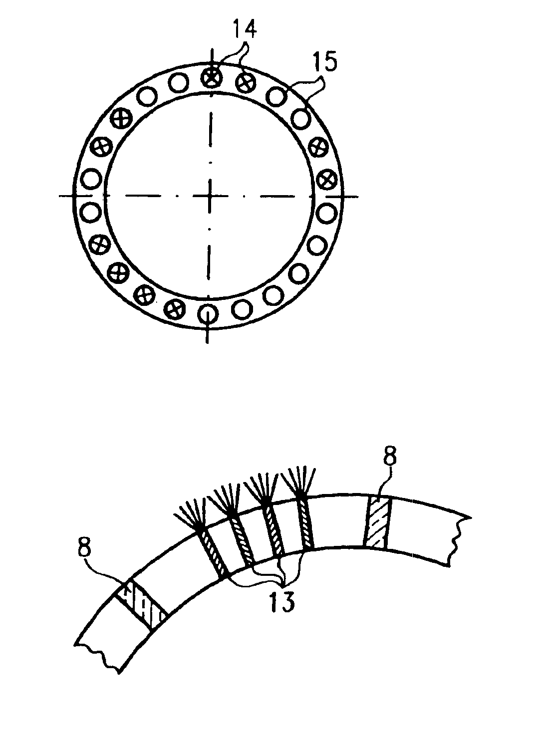
[0032]For easy reference, the parts have been labeled with the same numbers in the different versions of the invention.

[0033]This detailed description should be read in conjunction with the summary of the invention above.

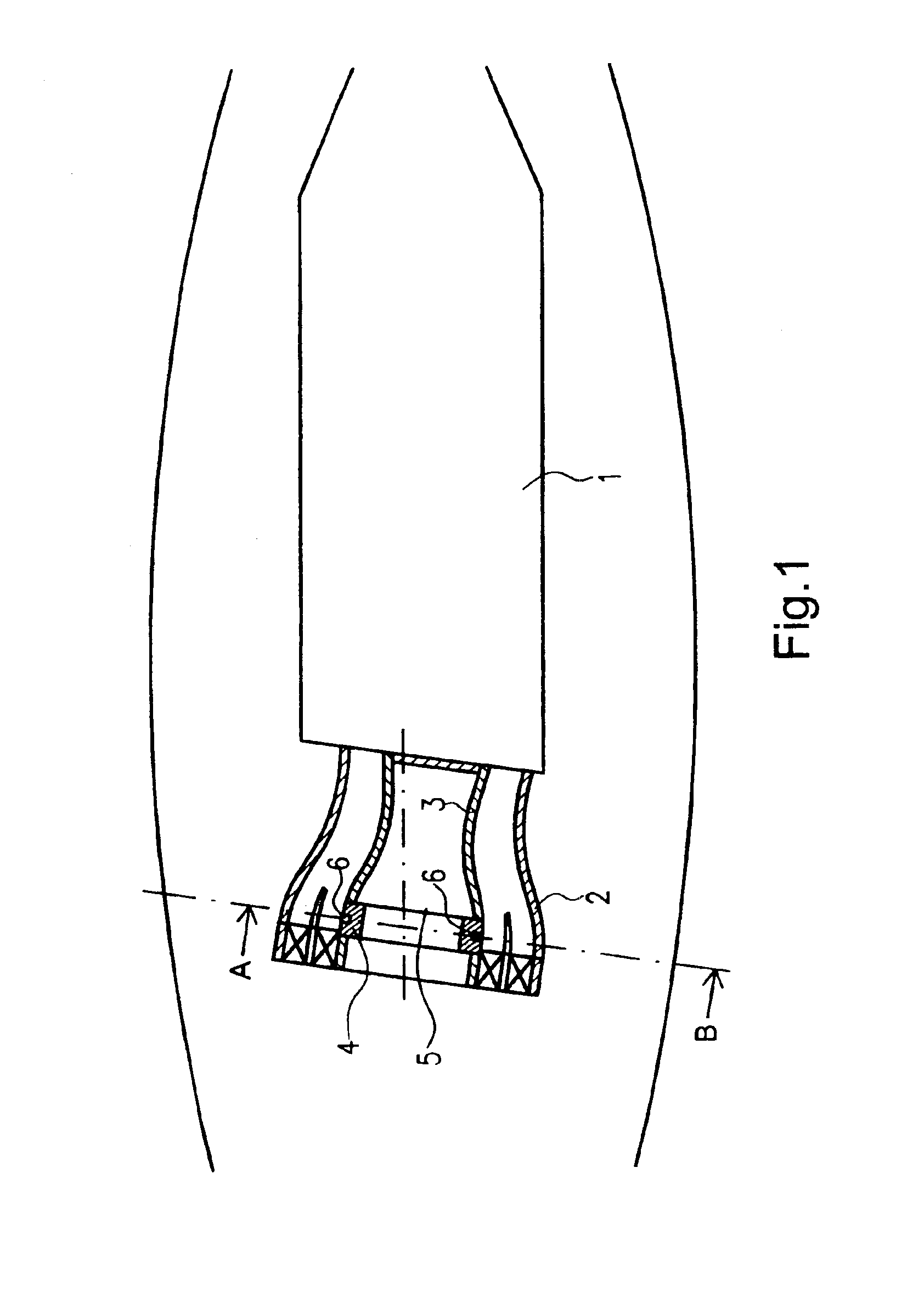
[0034]FIG. 1 shows a schematic lateral view of a lean premix module according to the invention in a gas turbine combustion chamber. Reference number 1 indicates a flame tube installed downstream from a lean premix burner; the burner consists of an outer casing 2 and an inner casing 3. The inner casing features a fuel nozzle ring 4. Reference number 5 indicates an internal structural element of the lean premix burner. Reference number 6 indicates the position of fuel nozzles in a generalized presentation.

[0035]The basic design and construction of such lean premix burners is known from state-of-the-art technology and therefore requires no further detailing here.

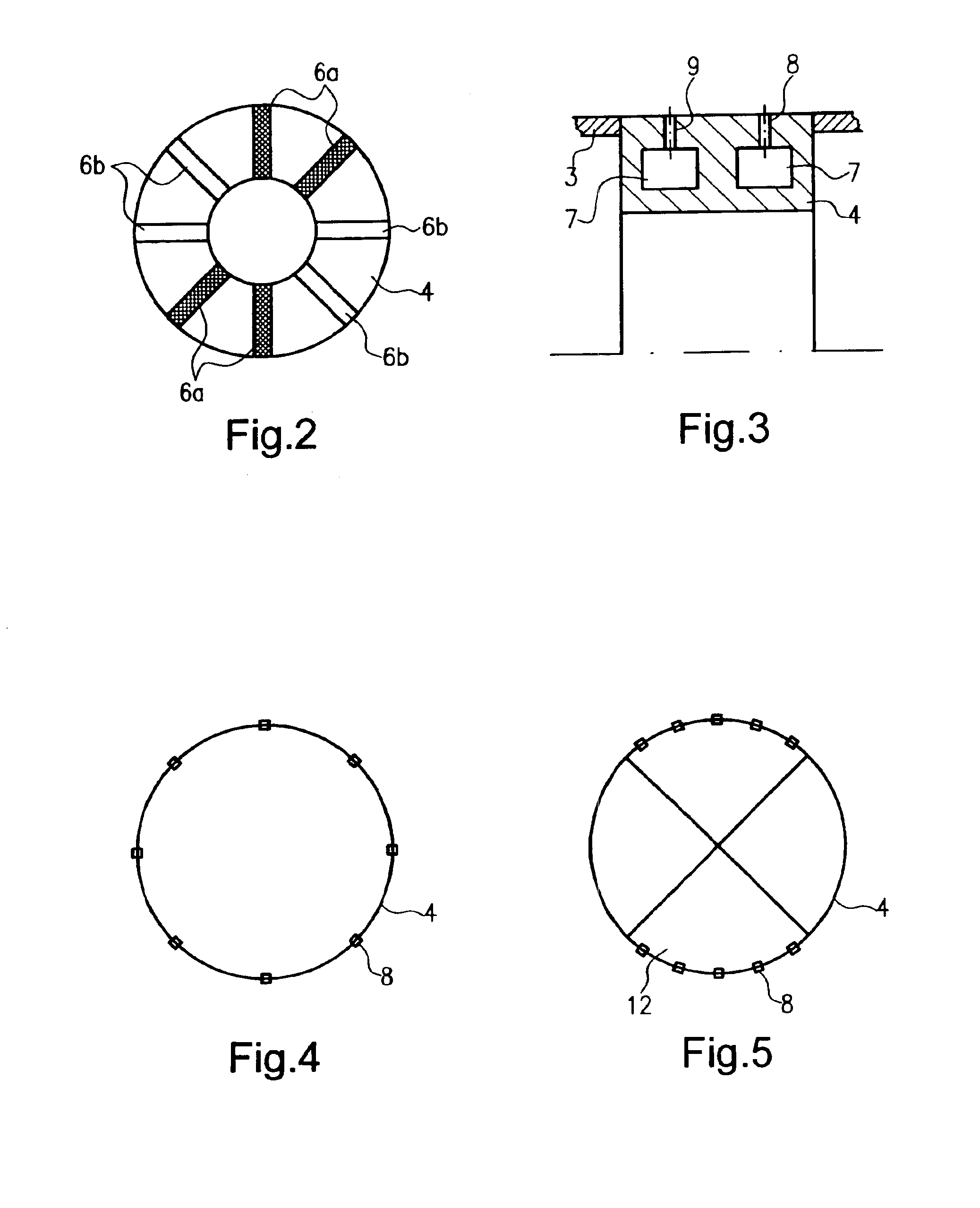
[0036]FIG. 2 shows a sectional view along line A-B in FIG. 1. Several fuel nozzles 6 are shown schematically...


PUM


Abstract

A lean premix burner for a gas turbine having at least one fuel supply ring 4 fitted with primary fuel nozzles 8 and additional secondary fuel nozzles 9, and a method of operation for this lean premix burner.

Description

[0001]This application claims priority to German Patent Application DE10160997.3, filed Dec. 12, 2001, the entirety of which is incorporated by reference herein.BACKGROUND OF THE INVENTION[0002]The invention comprises a lean premix burner for a gas turbine and a method of operating a lean premix burner.[0003]In detail, the invention comprises a lean premix burner with at least one fuel supply ring featuring primary fuel nozzles.[0004]Such a lean premix burner can be realized as either an LPP module or a swirlcup.[0005]Lean premix burners are known as state-of-the-art technology in a wide variety of designs and versions.[0006]Lean premix burners were developed, among other reasons, to avoid formation of nitrous oxides. For this purpose, the air-to-fuel ratio is set high so as to realize a very lean mixture in this process. This results in relatively low burning temperatures in the main burning zone.[0007]A potential drawback may result from the fact that the relatively low combustion...

Claims


Application Information

Patent Timeline
IPC IPC(8): F23R3/28F23R3/34
CPCF23R3/286F23R3/346F23C2201/20
Inventor VON DER BANK, RALF SEBASTIAN
Owner ROLLS ROYCE DEUT LTD & CO KG
Learn More