
Automatic flavor-injected blending apparatus and method

a technology of automatic blending and blending apparatus, which is applied in the direction of application, liquid transfer device, grain treatment, etc., can solve the problems of obviating the possibility of serving different-volume containers, requiring expensive retail space, and high cost of machines, so as to improve quality and improve quality.

Inactive Publication Date: 2005-09-20
ARCHIBALD BROS INT
View PDF40 Cites 73 Cited by
  • Summary
  • Abstract
  • Description
  • Claims
  • Application Information

AI Technical Summary

Benefits of technology

[0011]It is an additional object to provide such an apparatus and method that decreases human interaction time.
[0021]This system achieves an automatic process and apparatus therefor for mixing a comestible product in a container such as a cup, for example. The comestible may comprise, but is not intended to be limited to, a milk shake, fruit shake, smoothie, or frozen dessert. Since the blending process is automated, the server can start the apparatus, step away and attend to other duties while the apparatus is functioning, and return at a later time after the timer has turned off the spindle rotator. Further, an improved quality and perception of improved quality are both achieved, since the blending occurs at the time of order, and the consumer is served a freshly prepared product.

Problems solved by technology

Further, milk shake machines are available for use in fast-food-styled restaurants, but such machines are typically expensive.
In addition, storage of product used is typically within the machine thus demanding expensive retail space for placement and convenient use.
In the known prior art, such systems are calibrated to deliver a predetermined amount of flavoring, which obviates the possibility of serving different-volume containers.
Further, the currently known systems require manual holding and movement of the cup during the blending process, which in a fast-food-style environment is too time-intensive.

Method used


Image

  • Automatic flavor-injected blending apparatus and method
  • Automatic flavor-injected blending apparatus and method
  • Automatic flavor-injected blending apparatus and method

Examples


Embodiment Construction

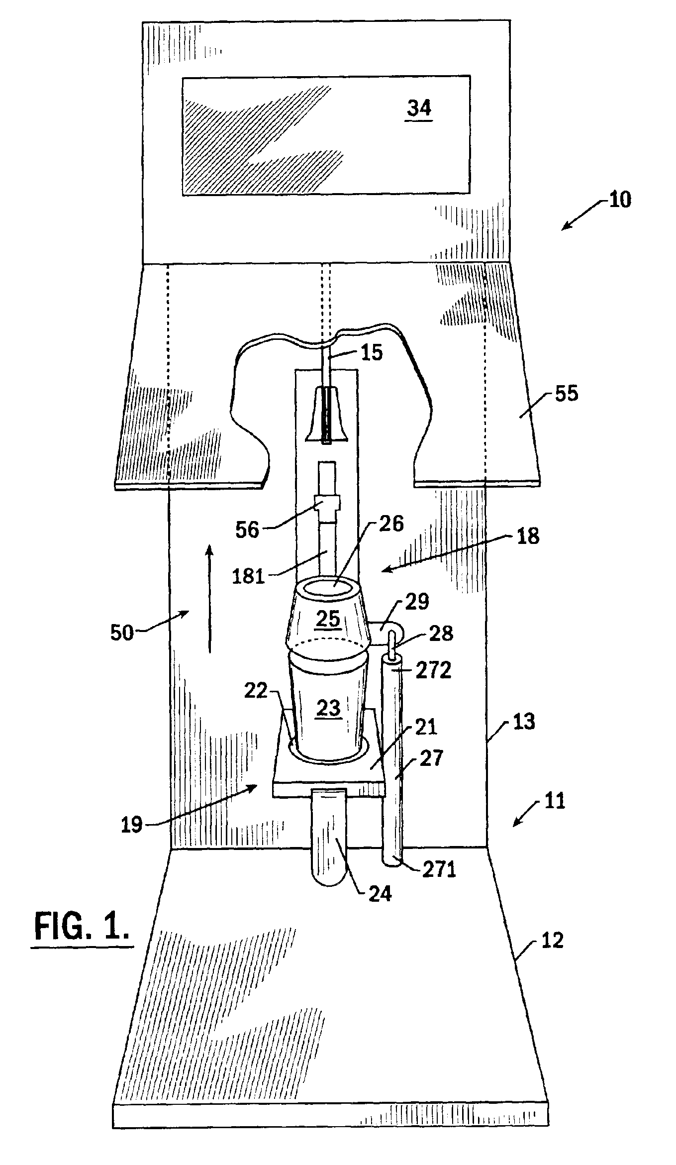
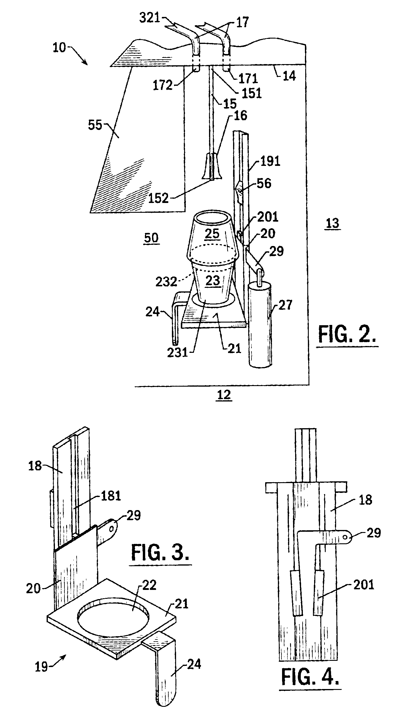
[0030]A description of the preferred embodiments of the present invention will now be presented with reference to FIGS. 1-6.

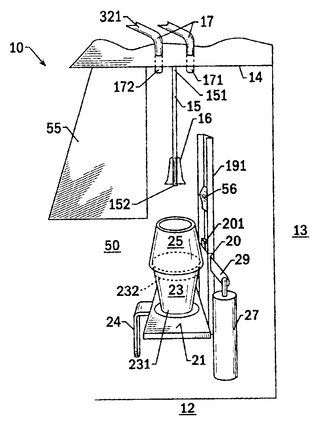
[0031]Front and side views of the apparatus 10 of the present invention are shown in FIGS. 1 and 2, and a schematic diagram in FIG. 7. The functions of the apparatus 10 are under control of a processor 30, which has resident thereon software 53 for performing the control calculations and functions (FIG. 10).

[0032]A base of the apparatus 10 comprises a housing 11 that has a substantially horizontal bottom 12 positionable on a serving surface such as a counter. A substantially vertical back 13 extends upward from a back edge of the bottom 12. A shelf 14 extending substantially horizontally forward of the back 13 and above the bottom 12 forms a space 50 enclosed on three sides. Depending from the underside of the shelf 14 at its upper end 151 is a rotatable spindle 15 that has a plurality of blending blades 16 adjacent a lower end 152. The spindle 15 is rotatable ...


PUM


Abstract

An automatic flavor-injected blending apparatus includes a base, a processor, and a user input in signal communication with the processor. A blending spindle is rotatably affixed at an upper end to the base and is rotatable under processor control. A container support is movably affixed to the base and is movable between a lower position for placing a container thereon and an upper position closer to the spindle's upper end. A selected flavor is injectable into the container. Software is resident in the processor that is adapted to receive the flavor selection and actuate the injection. The software is further adapted to actuate the spindle rotation. Since the blending process is automated, the server can start the apparatus, step away and attend to other duties while the apparatus is functioning, and return at a later time after a timer has turned off the spindle rotator.

Description

CROSS-REFERENCE TO RELATED APPLICATION[0001]This application claims priority from provisional application Ser. No. 60 / 283,124, “Automatic Flavor-Injected Blending Apparatus and Method,” filed Apr. 11, 2001.BACKGROUND OF THE INVENTION[0002]1. Field of the Invention[0003]The present invention relates generally to the dispensing and mixing of multi-flavored drinks and semisolid foods such as milkshakes, frozen custards, slushes, slurries, and the like, and more particularly to an efficient and cost effective method of preparing a flavored shake or slurry.[0004]2. Description of Related Art[0005]Beverage dispensing systems are used to provide consumers with beverages that are typically a mixture of previously stored concentrate and water. Further, milk shake machines are available for use in fast-food-styled restaurants, but such machines are typically expensive. In addition, storage of product used is typically within the machine thus demanding expensive retail space for placement and ...

Claims


Application Information

Patent Timeline
Patent Type & Authority Patents(United States)
IPC IPC(8): A23G9/22A23G9/04A23G9/28A47J43/04A47J43/042A47J31/41A47J31/40A47J43/044
CPCA23G9/04A23G9/045A23G9/225A23G9/28A23G9/283A47J31/41A47J43/042A47J2043/04463
Inventor BROWN, WILLIAMMILLER, ERIC R.
Owner ARCHIBALD BROS INT
Learn More