Wall panel and system

a wall display and accessory technology, applied in the field of wall display systems, can solve the problems of undesirable, wall display systems of this type offer no mobility of accessories, etc., and achieve the effect of facilitating alignment of the shaped attachment member

Inactive Publication Date: 2005-09-20
PRODS OF TOMORROW
View PDF80 Cites 177 Cited by
  • Summary
  • Abstract
  • Description
  • Claims
  • Application Information

AI Technical Summary

Benefits of technology

[0047]The back member may include an aperture to facilitate alignment of the shaped attachment member of the shelf with the shaped opening of the wall panel.

Problems solved by technology

This is typically undesirable as, for instance, when items are placed on, for example, a shelf, users may dislodge the shelf from the slatted wall when removing the items.
It is also undesirable because free space is required above or below an accessory to permit adequate space for the angled insertion.
Once inserted into a slot, these items are retained in a fixed position, as their fitting mechanisms do not allow for sliding along the slots.
Wall display systems of this type offer no mobility of the accessory once placed within an aperture.

Method used


Image

  • Wall panel and system
  • Wall panel and system
  • Wall panel and system

Examples


first embodiment

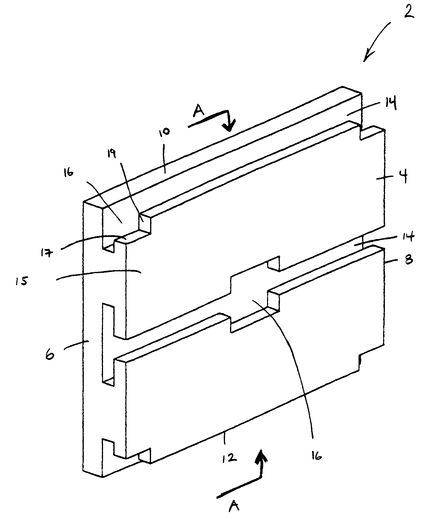
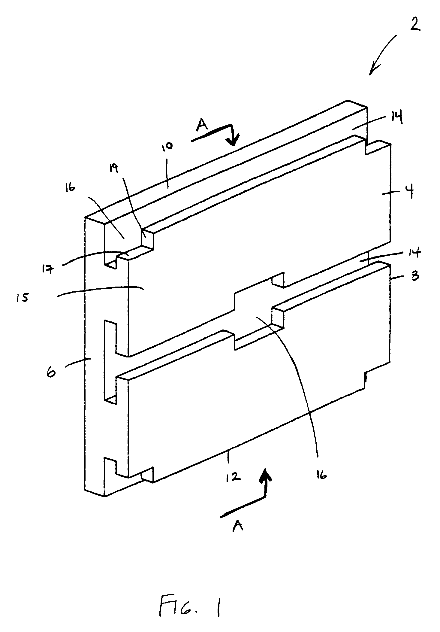
[0125]Referring to the figures, FIG. 1 depicts a perspective view of a wall panel 2 in accordance with the present invention. A portion of the front surface 4 is preferably planar or generally planar, and in one preferred embodiment a major portion of the front surface 4 of the entire front surface 4 is planar or generally planar. The panel 2 also includes first side edge 6 and second side edge 8. Extending between first side edge 6 and second side edge 8 are top edge 10 and bottom edge 12.

[0126]The wall panels 2 of one embodiment also include recessed slots 14 extending between the first side edge 6 and second side edge 8. Of course, a single panel may have one or more recessed slots. As shown in FIG. 1, the panel 2 includes a single slot (in the center) and portions of yet to be formed slots (on the upper end lower edges). The recessed slots 14 define slats 15 in the generally planar front surface 4 of the wall panel 2.

[0127]The slots 14 include an undercut which is in communicati...

third embodiment

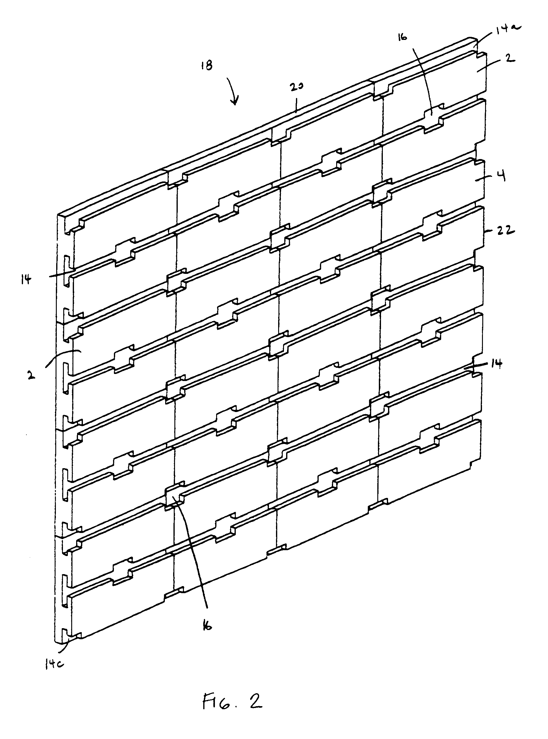
[0141]It will also be appreciated that the slatted wall panel 2 of the third embodiment may be designed to be either smaller or larger than the slatted wall panel 2 depicted in FIG. 6 without departing from the spirit or function of the present invention. Similarly, the number and spacing of shaped openings 16 and recessed slots 14 may vary in frequency.

[0142]The wall panel shown in FIG. 6 has three recessed slots 14 extending horizontally along the interior of the panel, a recessed slot bisected by the top edge 10, and a recessed slot bisected by the bottom edge 12. Each of these recessed slots 14 includes full or partial shaped openings 16, forming first ledges 17 and second ledges 19.

[0143]It will be noted that the slatted wall panel shown in FIG. 6 contains holes 34. These holes 34 are provided so that the slatted wall panel 2 may be affixed to the surface where it is intended to be used. Such affixation may be accomplished mechanically, such as with screws, bolts, nails or othe...

second embodiment

[0184]As shown in FIG. 27, additional elements provided in the second embodiment include a support plate 186 and an elongated rail 188 forming a portion of the T-shaped member 158. The elongated rail 188 along the back surface 190 of the support plate 186 provides a greater engagement surface area with the slots 14 of the slatted wall panel 2. This greatly enhances the rotational stability of the bracket 150. Meanwhile, the support plate 186 provides additional bearing surface area between the bracket 150 and the front surface of the slat wall 4. The support plate 186 may be a true plate as shown in FIG. 27, or a pair of built up shoulders adjacent the side surfaces 192 of the bracket 150. This general design also serves as a starting point for more elaborate accessories for the slatted wall panel 2.

[0185]FIG. 28 illustrates one such more elaborate accessory, a preformed shelf depicted as element 200. The shelf 200 comprises a back member 202 and a shelf member 204 extending perpend...


PUM


Abstract

A wall panel for holding an accessory, the wall panel having a recessed slot, at least a portion of which has an undercut and a shaped opening in communication with a portion of the recessed slot and the undercut. The shaped opening may be capable of receiving a shaped attachment member of an accessory, the shaped attachment member then being slidable within the undercut and the recessed slot beyond the limits of the shaped opening. A plurality of wall panels may be adapted to form a wall panel system.

Description

CROSS-REFERENCE TO RELATED APPLICATIONS[0001]This application claims the benefit of U.S. provisional application No. 60 / 419,741, filed Oct. 18, 2002 and expressly incorporates the disclosure of same by reference.BACKGROUND OF THE INVENTION[0002]The present invention relates to wall panels and wall panel systems. More particularly, the present invention relates to wall panels adapted to receive and retain detachable shelving hooks, and other accessories for displaying objects. Such wall panels and systems may be used to display merchandise in retail stores, display or store various items in residential homes or offices, as well as in other locations.[0003]Generally, such systems are well known in the art. Many such systems typically include a slatted wall panel with a number of recessed slots extending linearly along the front surface. These slots typically extend horizontally, the recessed slots being in communication with undercuts on the upper sides of the respective slots to form...

Claims


Application Information

Patent Timeline
Patent Type & Authority Patents(United States)
IPC IPC(8): A47F5/08
CPCA47F5/0846
Inventor STEVENS, KENNETH V.VALAORITIS, CONSTANTINE A.GILMAN, KEITH E.
Owner PRODS OF TOMORROW
Why Eureka
Try Eureka