Reverse buckling sanitary rupture disc assembly

a technology reverse buckling, which is applied in the direction of transportation and packaging, functional valve types, containers, etc., can solve the problems of difficult cleaning of processing equipment with steam or the like, and achieve the effects of reducing the number of sanitary rupture discs

Inactive Publication Date: 2005-09-20
FIKE CORP
View PDF18 Cites 48 Cited by
  • Summary
  • Abstract
  • Description
  • Claims
  • Application Information

AI Technical Summary

Benefits of technology

[0017]Next, either the deflection post is removed from the pre-bulging fixture, or the preformed blank is positioned in a separate final bulging non-post fixture. Sufficient pressure is applied to the concave surface of the pre-bulged disc to effect final bulging of the central section of the disc and at the same time return the indentation previously formed in the disc to its initial position with respect to the remainder of the disc body prior to formation of the indentation in the disc body by the deflection post. As a result, both the convex and concave surfaces of the disc are smooth and free of projecting surfaces or depressions that could collect materials thereon or therein, thus interfering with or impeding cleaning of the equipment with a sanitizing agent such as steam.
[0018]The two step process of first forming an indentation of predetermined extent and depth in the portion of the blank body that is to be bulged, and then removing the indentation by returning the metal of the indentation to its initial position causes the area that has been indented and then restored to have a higher residual stress than the remainder of the final bulged section of the disc, as a result of the plastic deformation of the metal in the segment region. The segment region, which has an altered grain structure, is relatively small compared with the overall area of the bulged section, is work hardened and exhibits a higher tensile and compressive strength, thus behaving differently during use than the remainder of the bulged section when an overpressure is applied to the convex face of the rupture disc.

Problems solved by technology

As a result, cleaning of the processing equipment with steam or the like is difficult and may require breakdown of the components in which the rupture disc is positioned in order to insure removal of material that may have collected in the depressed segment region.

Method used


Image

  • Reverse buckling sanitary rupture disc assembly
  • Reverse buckling sanitary rupture disc assembly
  • Reverse buckling sanitary rupture disc assembly

Examples


example

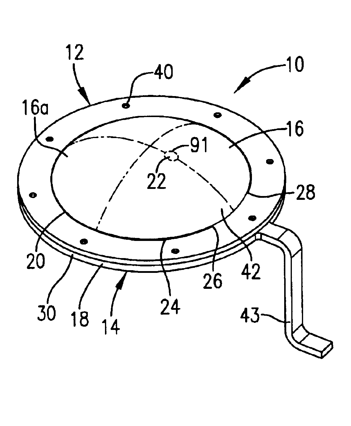
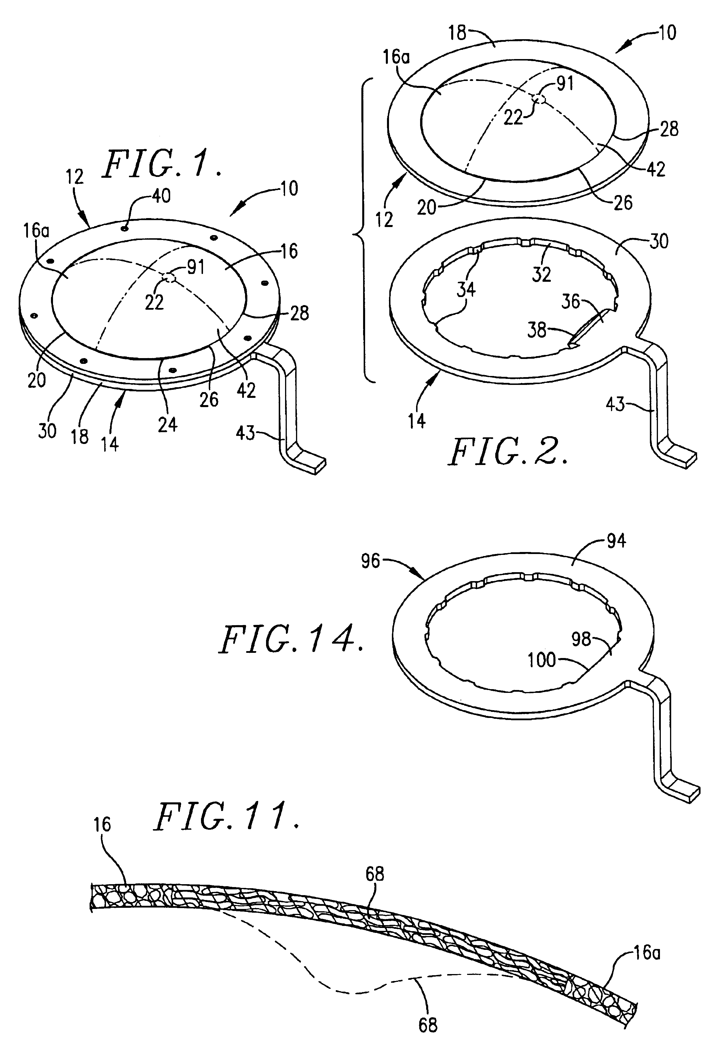
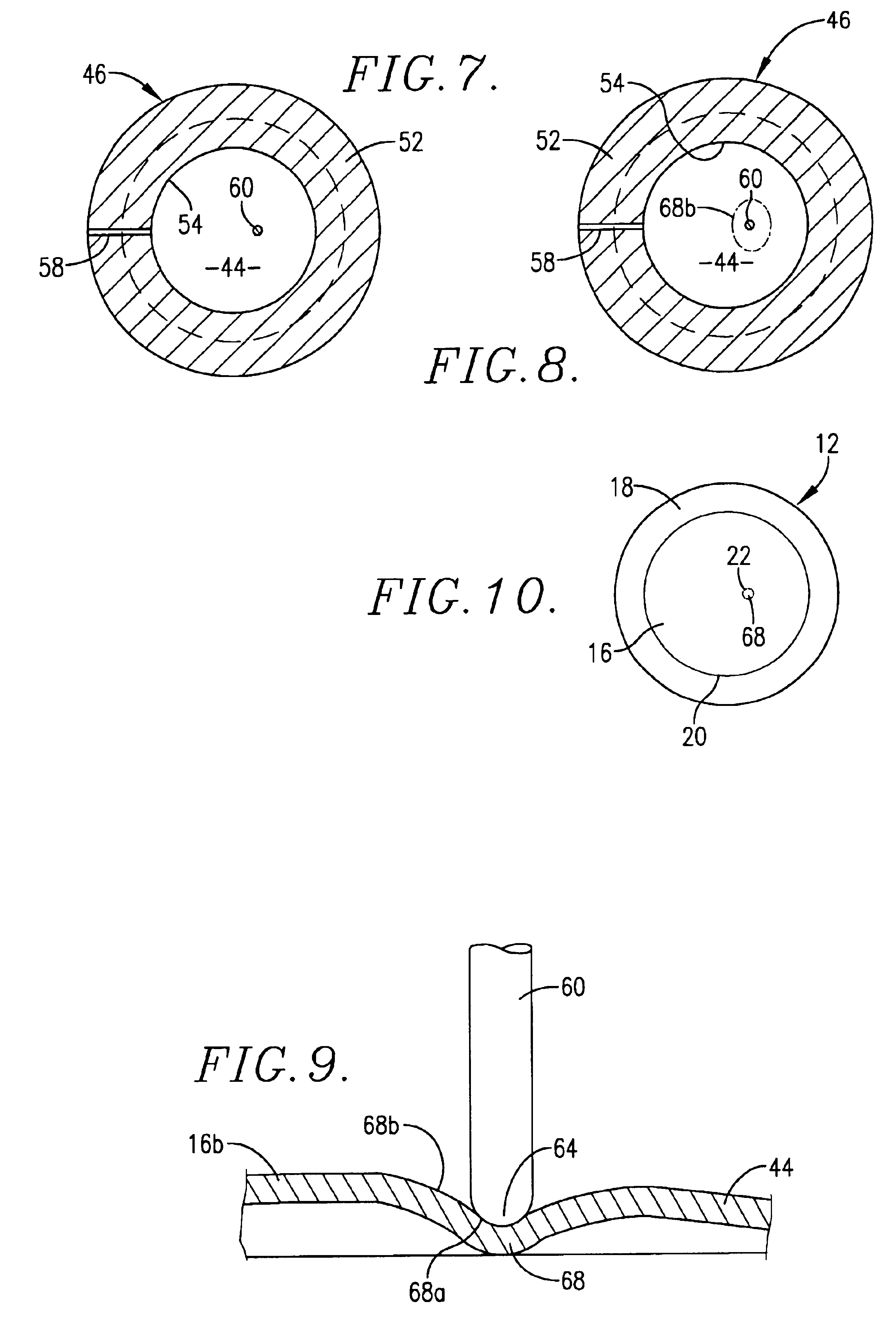
[0051]An exemplary disc 12 prepared in accordance with the preferred process of this invention and depicted in FIG. 10 is preferably fabricated from 2 mil 316 stainless steel and has an overall diameter of about 2.5 inches. Pre-bulging of the disc 12 as schematically illustrated in FIG. 4 is accomplished under a pressure of about 50 psig to form a depression 68 in the disc blank 44 as shown in FIG. 4. Final bulging of the disc as schematically shown in FIGS. 5 and 6 is carried out under a pressure of about 200 psig producing a bulged disc in which the height of the dome is about 0.34 inch. The outer boundary 91 (of FIG. 10) of the metal segment region 68 of the bulged section of the disc, which has been subjected to greater stress than the remaining metal of the bulged section 16 has a nominal area of about 0.4 square inch. The segment region 68 in the exemplary disc is spaced from the central axis of bulged section 16 about 0.3 inch. This disc has a nominal burst pressure of about ...


PUM

PropertyMeasurementUnit
pressuresaaaaaaaaaa
pressuresaaaaaaaaaa
diameteraaaaaaaaaa

Abstract

A metal reverse buckling sanitary rupture disc is provided having a central bulged section in which the convex surface of the bulged section is relatively smooth and of substantially uninterrupted configuration. A small segment region of the central bulged section is strain hardened by plastic deformation causing the segment region to have greater residual stress than the remainder of the central bulged section. When the disc is subjected to an overpressure condition against the convex surface of the bulged section sufficient to effect reversal of the bulged section, such reversal commences at the higher residual stress segment region of the bulged section.

Description

BACKGROUND OF THE INVENTION[0001]1. Field of the Invention[0002]This invention relates to a reverse buckling rupture disc assembly especially adapted for use in sanitary pressure vessel piping applications where the disc reliably ruptures under overpressure conditions.[0003]Pharmaceutical, biochemical and food processing equipment require that sanitary conditions be maintained at all times, which necessitates frequent cleaning of the equipment, usually with steam or other sanitization agents. These processes often are operable at relatively low pressures in which overpressures in the equipment or piping connected thereto must be relieved at levels as low as about 2 psig up to about 50-60 psig. It is conventional to employ reverse buckling rupture discs for applications, but it has been found difficult to provide narrow range burst pressure tolerances at these ranges.[0004]In order to accomplish reliable disc rupture at low differential pressures, it has now been found that a require...

Claims


Application Information

Patent Timeline
Patent Type & Authority Patents(United States)
IPC IPC(8): F16K17/02F16K17/16B21D26/021B21D26/047B21D26/049
CPCF16K17/1606Y10T292/481
Inventor KREBILL, MICHAEL D.MILLER, E. DEAN
Owner FIKE CORP
Why Eureka
Try Eureka