Cryogenic coupling device

a coupling device and cryogenic technology, applied in the direction of couplings, liquid handling, packaging goods types, etc., can solve the problems of large time and effort required components are also fairly complicated to manufacture and assemble, and the above-mentioned coupling device has a number of components which are fairly complicated, so as to prevent spills and reduce the clearance necessary. , the effect of small siz

Active Publication Date: 2005-09-20
PARKER INTANGIBLES LLC
View PDF27 Cites 36 Cited by
  • Summary
  • Abstract
  • Description
  • Claims
  • Application Information

AI Technical Summary

Benefits of technology

[0007]The present invention thereby provides an improved coupling device, particularly suitable for cryogenic fluids, which is robust, able to withstand harsh fueling environments, prevents spills, has a small size to reduce the clearance necessary for coupling the nozzle to the receptacle, and has many of the other features and advantages of prior coupling devices, but which is also simpler and easier to manufacture and assemble; is easier to rebuild; and has an improved interface seal design with an extended service life. The coupling device also has a unique coupling structure which securely couples the nozzle to the receptacle and allows venting of the coupling before full disconnect.

Problems solved by technology

Nevertheless, the above described coupling device has a number of components which are fairly complicated, and require significant time and effort to manufacture and assemble, as well as to rebuild during normal repair and maintenance.
The components are also fairly complicated to manufacture and assemble.

Method used


Image

  • Cryogenic coupling device
  • Cryogenic coupling device
  • Cryogenic coupling device

Examples


Embodiment Construction

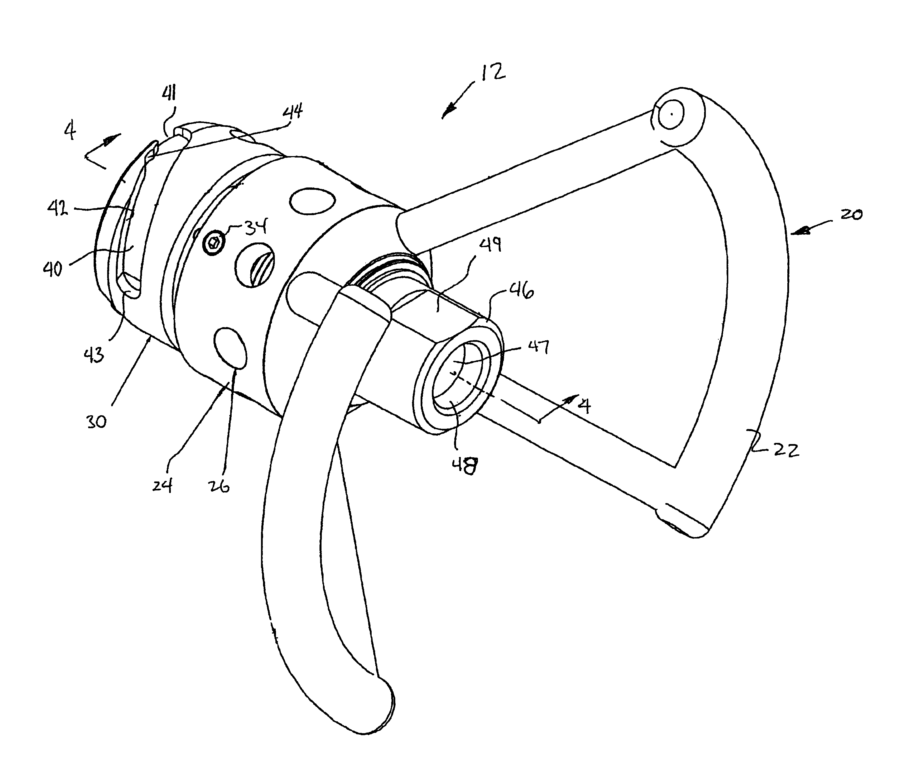
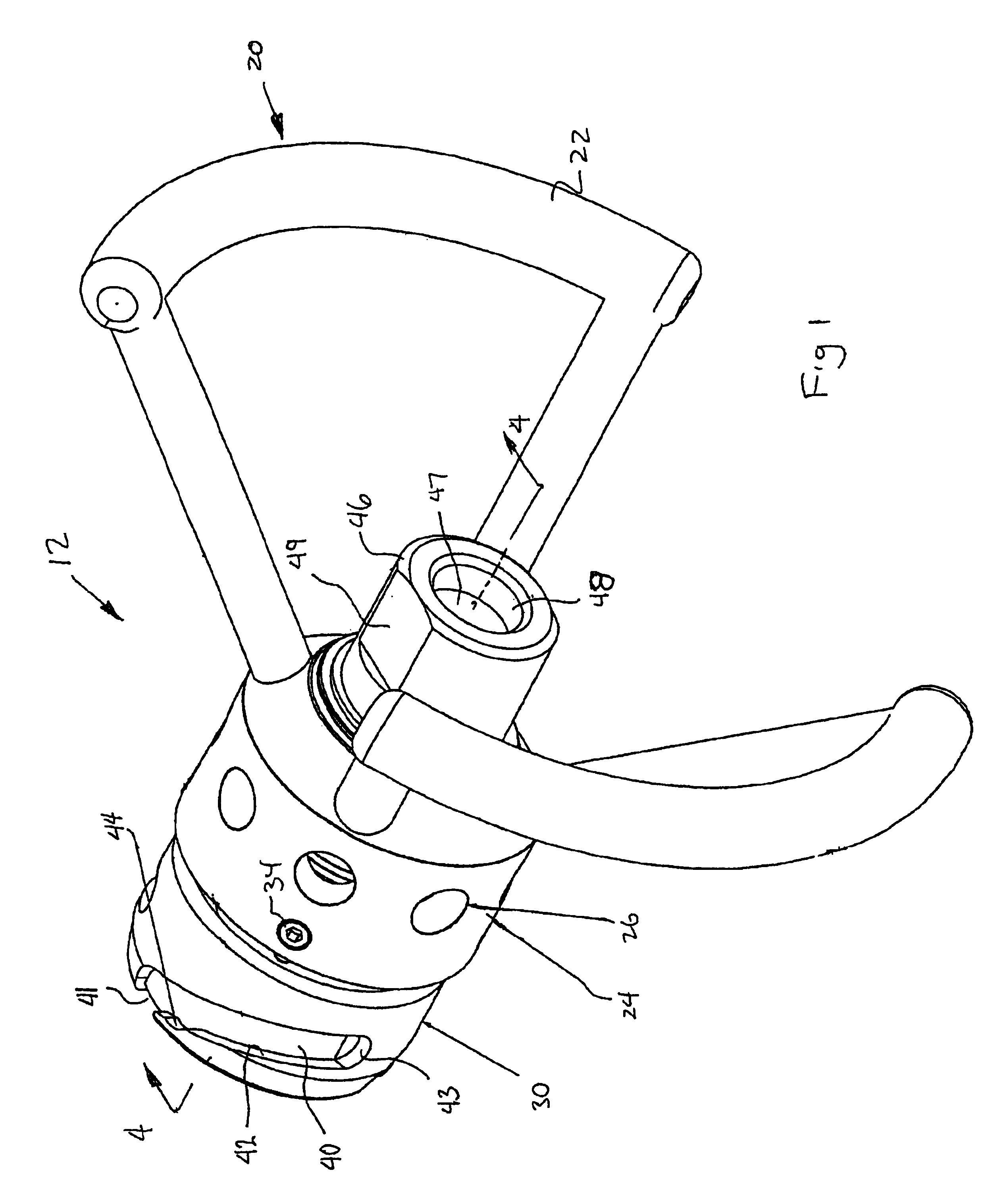
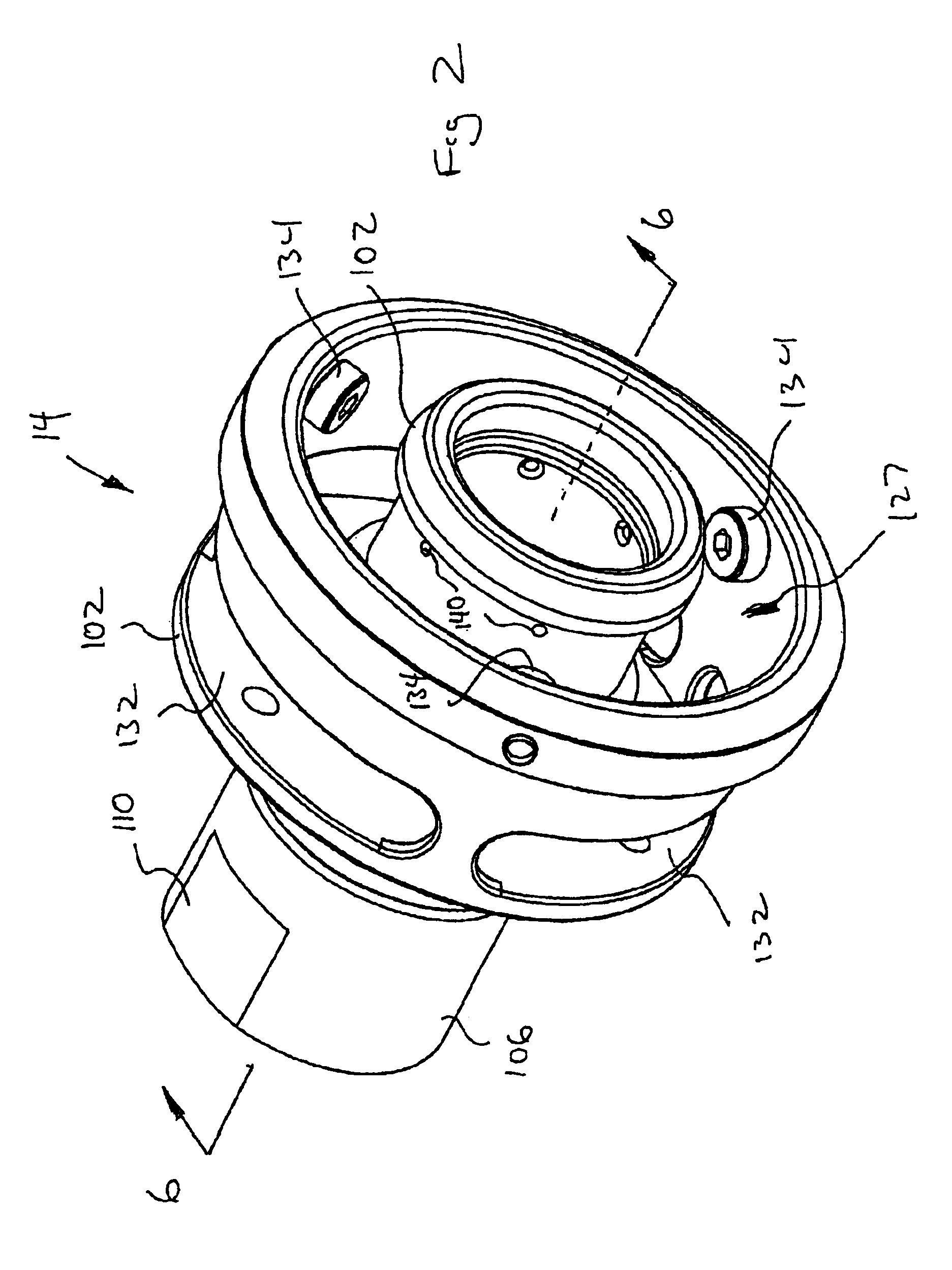
[0024]Referring to the drawings and initially to FIGS. 1-3, a coupling device is indicated generally at 10, and includes a nozzle, indicated generally at 12, and a receptacle, indicated generally at 14. The nozzle 12 and receptacle 14 are formed of appropriate materials, such as hardened stainless steel. The coupling device of the present invention is particularly useful for coupling together fluid lines for use in transferring fluid such as cryogenic fluids, from one tank or container to another; however, it should be appreciated that the present invention could be used for a variety of fluids and is not necessarily limited to cryogenic fluids. Likewise, although the coupling device is particularly useful for coupling together fluid lines for use in transferring fluid from a storage tank to a mobile tank or container such as found on a vehicle or aircraft, these are only a few examples of such use, and the coupling device could be used in a wide variety of applications to transfer ...


PUM

PropertyMeasurementUnit
lengthaaaaaaaaaa
circumferenceaaaaaaaaaa
dimensionsaaaaaaaaaa

Abstract

A cryogenic coupling device includes a valved receptacle and a valved nozzle. Rollers in an outer collar of the receptacle are received in helical channels along a collar of the nozzle. A notch or detent in each of the channels provides a vent position to vent fluid before the nozzle is fully disconnected from the receptacle. Interface seals on the nozzle include first and second annular seals that function as ice and containment scrapers, as well as fluid seals. The nozzle has a rotatable handle assembly, isolated from the fluid path, which provides easy connect and disconnect of the nozzle from the receptacle. The handle assembly includes a thermal break, and is easily removable from the nozzle, along with other parts of the nozzle and receptacle, for service and maintenance.

Description

CROSS-REFERENCE TO RELATED CASES[0001]The present application claims the benefit of the filing date of U.S. Provisional Application Ser. No. 60 / 408,388; filed Sep. 4, 2003, the disclosure of which is expressly incorporated herein by reference.FIELD OF THE INVENTION[0002]The present invention relates generally to valved nozzles which mate with valved receptacles to transfer fluids such as cryogenic fluids.BACKGROUND OF THE INVENTION[0003]Coupling devices are known for transferring fluids from a storage tank into a mobile tank or other container such as found on an automobile, bus, truck, aircraft, etc. For certain fluids, for example, cryogenic fluids (e.g., liquid nitrogen, liquid argon, liquid oxygen), the coupling must be robust and able to withstand particularly difficult fueling environments (e.g., it must prevent coupling freeze-up). It is also important that the coupling prevent spills and have dimensions which minimize the clearance necessary for coupling the nozzle to the re...

Claims


Application Information

Patent Timeline
Patent Type & Authority Patents(United States)
IPC IPC(8): F16L37/00F16L37/252
CPCF16L37/252F16L37/32F17C2205/037
Inventor LAMBERT, TODD D.ANDERSON, KEITH J.
Owner PARKER INTANGIBLES LLC
Why Eureka
Try Eureka