
Fence caps for a fencing system

a fencing system and fencing technology, applied in the field of fencing caps, can solve the problems of weakening the physical structure of the fence, many caps which may be used on such fencing systems are not aesthetically pleasing, and many caps are not sufficient to prevent the ingress of weather, water, moisture, insects and small animals, etc., to achieve the effect of facilitating the attachment of caps, increasing strength, and increasing resistance against accidental disassembly of members

Inactive Publication Date: 2005-09-20
DIPASQUALE GIUSEPPE
View PDF14 Cites 11 Cited by
  • Summary
  • Abstract
  • Description
  • Claims
  • Application Information

AI Technical Summary

Benefits of technology

[0005]The present invention overcomes and eliminates the drawbacks described above by providing fence cap members which may be incorporated in a fence structure to cap the openings which may be present at the top and ends of a fence. Such a fence cap includes at least first and second recesses located on each side of the fence cap. Fence sidings may be insinuated into and received by these first and second recesses in order to facilitate the attachment of the caps to the fence and properly cover the openings at the top and ends of the fence. The fence caps of the present invention may be molded as one piece so as to provide increased strength and increased resistance against accidental disassembly of the members and further to aid in preventing ingress of water, moisture, and insect and animal life.

Problems solved by technology

Further, when made with particular materials, the various members comprising the fence sides may be susceptible to warping, which disrupts the appearance of the fence, and may weaken the physical structure of the fence.
Many caps which may be used on such fencing systems are not aesthetically pleasing in that the attachment points are visible on the outside of the fence.
Further, many caps are not sufficient to prevent the ingress of weather, water, moisture, or insects and small animals.
Also, fence systems generally do not include caps formed to cover the openings located at the ends of fences.

Method used


Image

  • Fence caps for a fencing system
  • Fence caps for a fencing system
  • Fence caps for a fencing system

Examples


first embodiment

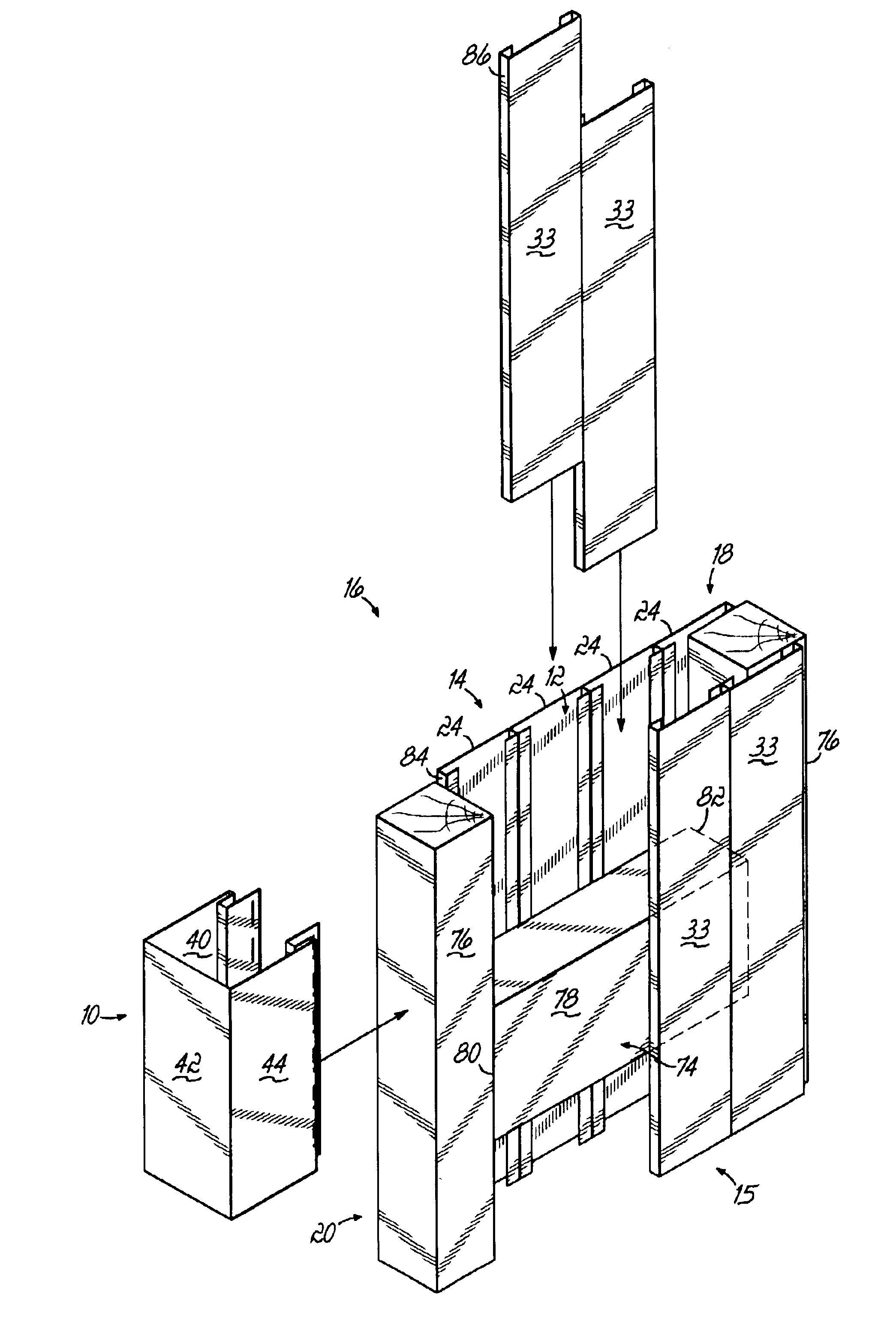
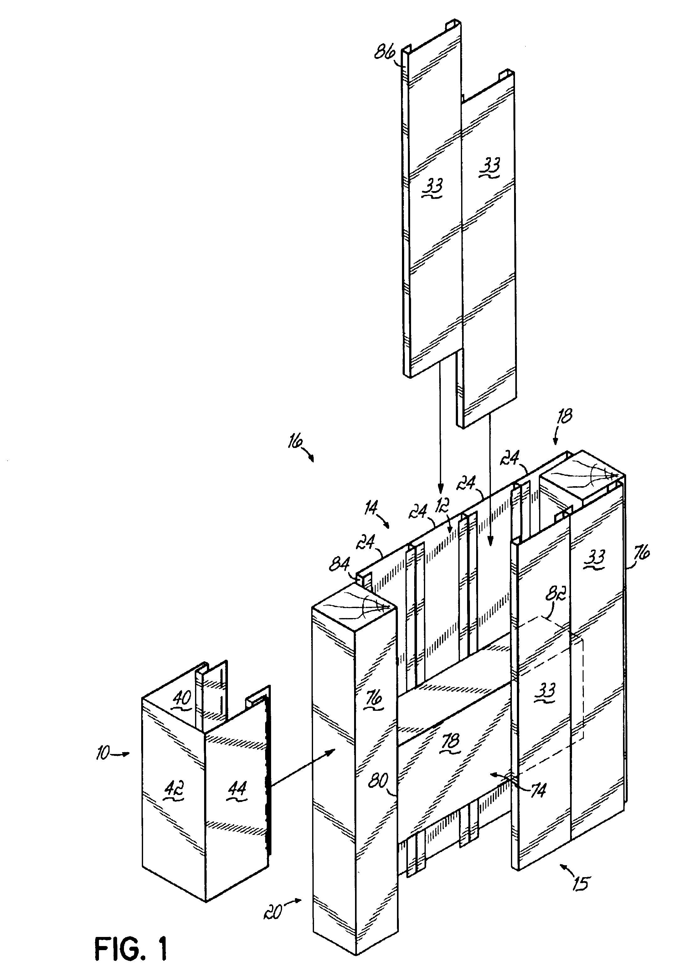
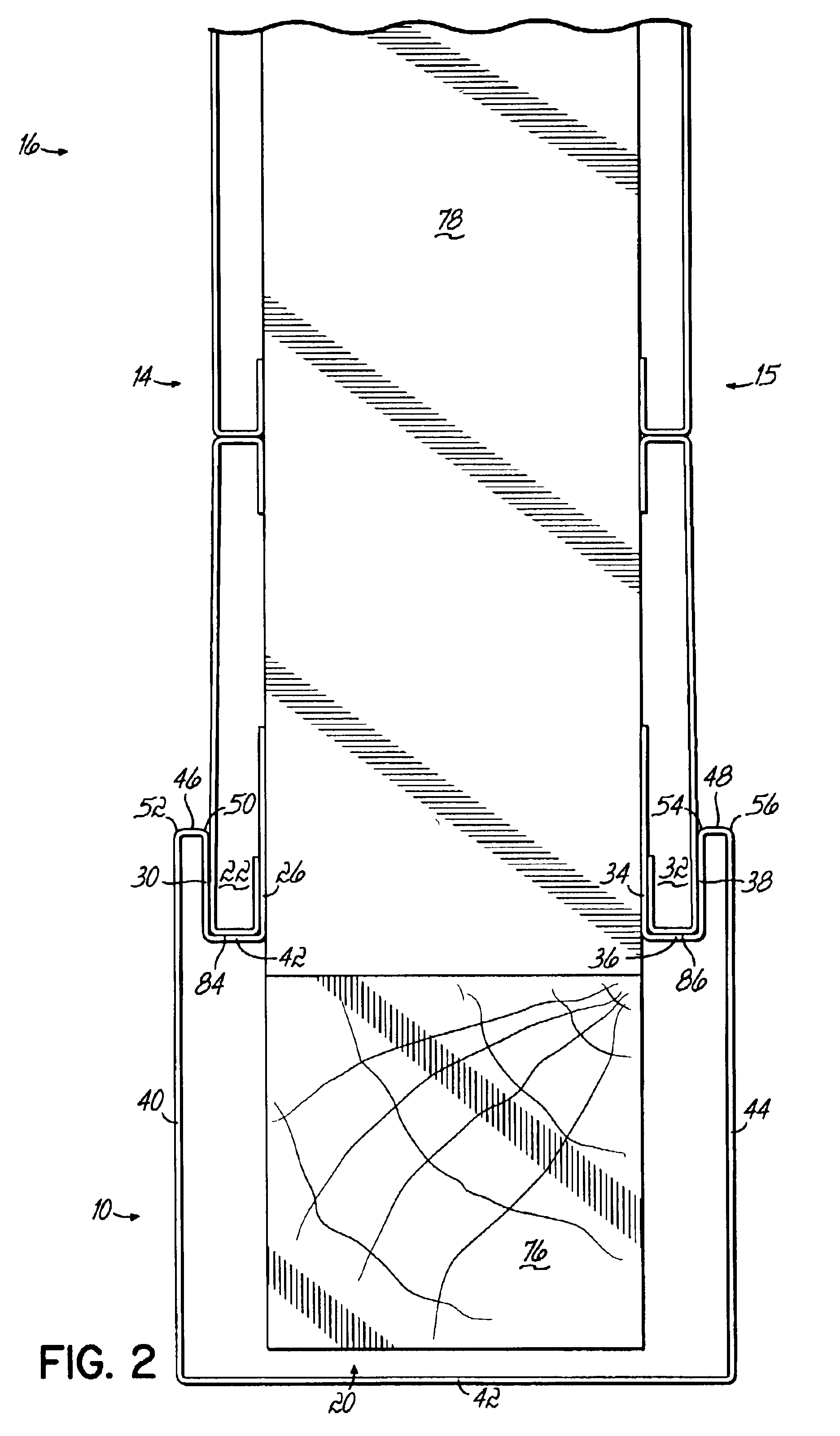
[0023]Referring now to FIGS. 1-2A, the fence cap 10 of the present invention may be used to cover the opening 12 of a fence structure on the end of a fence 16. This embodiment includes first and second recesses 22, 32, as described above, each adapted to receive first and second components 24, 33 of a fence 16, respectively. The fence cap 10 thus includes first, second, and third walls 26, 28, 30 defining the first recess 22, wherein the first wall 26 and third wall 30 are substantially parallel one to another, and the first wall 26 and third wall 30 are each substantially perpendicular to the second wall 28. The fence cap 10 thus further includes fourth, fifth, and sixth walls 34, 36, 38, defining the second recess 32, wherein the fourth wall 34 and sixth wall 38 are substantially parallel one to another, and the fourth wall 34 and the sixth wall 38 are each substantially perpendicular to the fifth wall 36. The third wall 30 and the sixth wall 38 are substantially parallel one to a...

second embodiment

[0025]Referring now to FIGS. 3-4, the fence cap 10 of the present invention may be used to cover the opening 12 of a fence structure on the top 18 of a fence 16. In this illustrated embodiment, like components are represented by like numbers. This embodiment includes first and second recesses 22, 32, as described above, adapted to receive first and second components 24, 33 of a fence 16. The fence cap 10 thus includes first, second, and third walls 26, 28, 30 defining the first recess 22, wherein the first wall 26 and third wall 30 are substantially parallel one to another, and the first wall 26 and third wall 30 are each substantially perpendicular to the second wall 28. The fence cap 10 thus further includes fourth, fifth, and sixth walls 34, 36, 38 defining the second recess 32, wherein the fourth wall 34 and sixth wall 38 are substantially parallel one to another, and the fourth wall 34 and the sixth wall 38 are each substantially perpendicular to the fifth wall 36. The third wa...

third embodiment

[0027]Referring now to FIGS. 5-7, the present invention may be used to cover the opening 12 of a fence structure on the top 18 of a fence 16 proximal to the end 20 of a fence section. In the illustrated embodiment, like components are represented by like numbers. This embodiment includes first and second recesses 22, 32, as described above, adapted to receive first and second components 24, 33 of a fence 16. The article thus includes first, second, and third walls 26, 28, 30 defining the first recess 22, wherein the first wall 26 and third wall 30 are substantially parallel one to another, and the first wall 26 and third wall 30 are each substantially perpendicular to the second wall 28. The article thus further includes fourth, fifth, and sixth walls 24, 36, 38, defining the second recess 32, wherein the fourth wall 34 and sixth wall 38 are substantially parallel one to another, and the fourth wall 34 and the sixth wall 38 are each substantially perpendicular to the fifth wall 36. ...


PUM


Abstract

In general, the present invention includes a fence cap for covering the openings between two sides of a fence at the top of the fence and / or the end of the fence. The fence cap includes a first recess adapted to receive a first component of a fence. This first recess is defined by a first wall, a second wall, and a third wall. The first wall and the third wall are substantially parallel one to another, and the first wall and the third wall are each substantially perpendicular to the second wall. The cap further includes a second recess adapted to receive a second component of the fence. This second recess is defined by a fourth wall, a fifth wall, and a sixth wall. The fourth wall and the sixth wall are each substantially parallel one to another, and the fourth wall and the sixth wall are each substantially perpendicular to the fifth wall. In the fence cap of the present invention, the third wall and the sixth wall are substantially parallel one to another.

Description

FIELD OF THE INVENTION[0001]The present invention generally concerns articles to be used as components for a fencing system.BACKGROUND OF THE INVENTION[0002]Many fences include sides including a plurality of members that are positioned in vertically or horizontally disposed rows. Fences may include two such sides positioned on both sides of an inner frame of the fence. In a typical fence structure, a number of central support posts, formed from 4″×4″s, for example, are located a predetermined distance one from another. At least one board, and generally a plurality of boards, such as 2″×4″s, are positioned between each of the successive central support posts in order to create the inner frame of the fence. A plurality of fence siding members may then be attached to this fence frame in order to provide the outer surface or surfaces of the fence. These siding members may be added to both sides of the fence frame. In one embodiment, these fence materials may be vinyl extruded siding suc...

Claims


Application Information

Patent Timeline
Patent Type & Authority Patents(United States)
IPC IPC(8): E04H17/16E04H17/00
CPCE04H17/16E04H2017/006E04H17/006E04H17/00
Inventor AUGUR, JAMES D.
Owner DIPASQUALE GIUSEPPE
Learn More