System of laser positioning of an aperture processing machine

a technology of aperture processing machine and laser positioning, which is applied in the direction of manufacturing tools, lighting and heating equipment, instruments, etc., can solve the problems of difficult to guarantee the accuracy of the aperture position, labour and time-consuming adjustment, and eye fatigue of the operating worker, etc., to achieve the effect of low cost, convenient use and rapid adjustmen

Active Publication Date: 2005-09-20
QINGDAO D&D INTELLECTUAL TECH CO LTD
View PDF12 Cites 5 Cited by
  • Summary
  • Abstract
  • Description
  • Claims
  • Application Information

AI Technical Summary

Benefits of technology

[0017]The present invention has the advantages of rapidity, accuracy, low cost and ease of use. It can be used widely in processing machines such as drilling machines, lathes and boring lathes.

Problems solved by technology

The adjustment is labour and time-consuming and easily leads to eye fatigue for the operating worker.
Besides, it is difficult to guarantee the precision of the position of the aperture.

Method used


Image

  • System of laser positioning of an aperture processing machine
  • System of laser positioning of an aperture processing machine
  • System of laser positioning of an aperture processing machine

Examples


embodiment 1

Preferred Embodiment 1

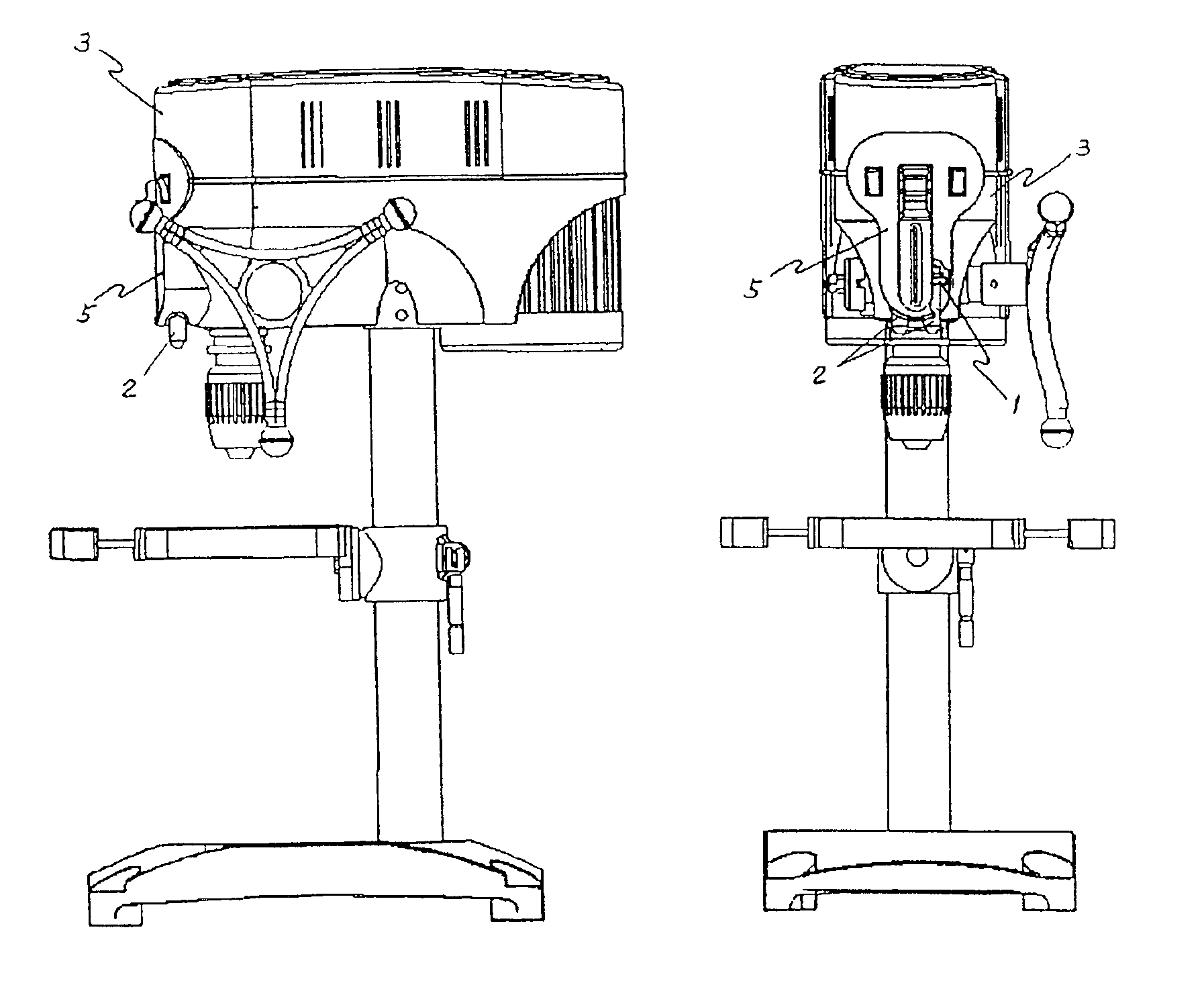
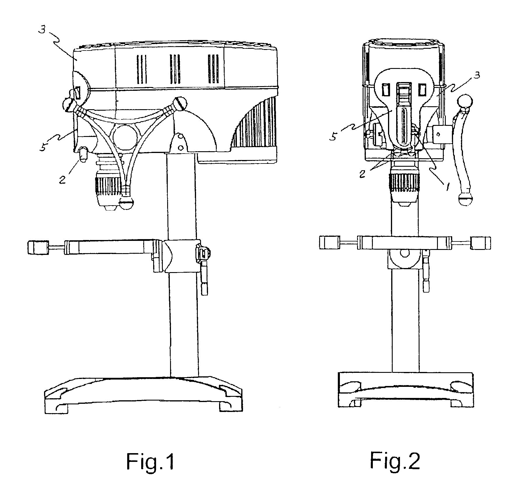
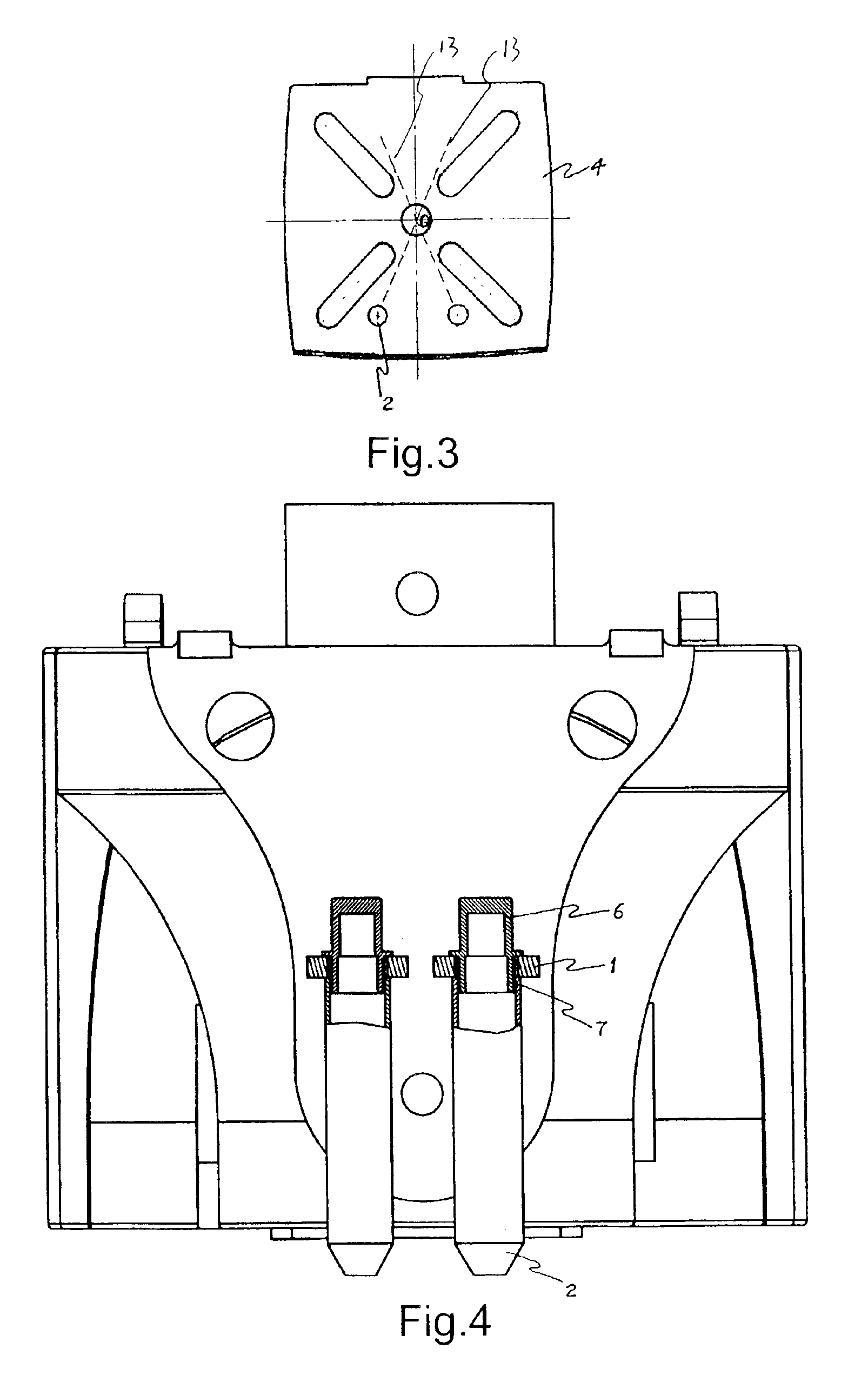
[0025]The present invention is a type of system of laser positioning of an aperture-processing machine. As shown in FIG. 5, there are two laser transmission devices (2). Each laser transmission device (2) emits a light beam (13). The two light beams (13) form an angular set up. Their point of intersection in space forms a common line of intersection (8). After both laser transmitting devices (2) are fixed relative to the aperture-processing machine, the common line of intersection (8) formed at the point of intersection of the two light beams (13) mentioned above coincides exactly with the axial line of the cutter centre of the aperture-processing machine, forming the point of reference for positioning.

[0026]In the present invention, the light beams (13) transmitted by the laser transmission devices (2) mentioned above are planar. The relative vertical projection of the said planar beam (13) is a fine, straight line (9). Therefore, the two planar beams (13) sho...

embodiment 2

Preferred Embodiment 2

[0036]As shown in FIG. 7, the difference between the present example and the above-mentioned example lies in the fact that the said laser transmission device (2) can be composed of a semiconductor-laser-diode-type laser transmitter (10) and beam expander. The beam expander can be composed of a convex lens (11) and a corrugated lens (16). The convex lens (11) and the corrugated lens (16) are set up along the axial line of the cylindrical laser beam mentioned. The semiconductor-laser-diode-type laser transmitter (10) can emit an extremely fine cylindrical beam (15). After penetrating through the said beam expander, this cylindrical beam (15) is expanded to become a planar light beam (13) and emitted.

[0037]In the present preferred embodiment, it is possible to adjust the position of the planar light beam (13) by the way described in the preferred embodiment 1. The adjustment of position of the plane of the light beam (13) can also be achieved through the regulatio...


PUM

PropertyMeasurementUnit
symmetryaaaaaaaaaa
angleaaaaaaaaaa
heightaaaaaaaaaa

Abstract

The present invention relates to a laser positioning system for an aperture-processing machine and is an accessory of an aperture-processing machine. The present invention is a type of laser positioning system for an aperture-processing machine that includes two laser transmission devices each of which emits a beam of light. The two light beams form an angular set up. A common line of intersection is formed at the point of intersection in space. After the two laser transmission devices have been fixed relative to the aperture-processing machine, the common line of intersection formed at the point of intersection of the two light beams mentioned above and the axial line of the main bearing cutter of the aperture-processing machine coincide exactly, thus forming the reference for positioning. In the application of the present invention, adjustment is easy, positioning is rapid and observation is direct with high accuracy and low cost. The device can be used widely in processing machines such as drilling machines, boring lathes and lathes.

Description

BACKGROUND OF THE INVENTION[0001]1. Field of the Invention[0002]The present invention relates to an aperture-processing machine, and in particular, a system of laser positioning in an aperture-processing machine used for locating the position of the aperture that is being processed on a work piece accurately.[0003]2. Description of the Prior Art[0004]At present, when aperture-processing machines such as the drilling machine and lathe are used for aperture processing, in general, lines have to be drawn on the work piece to be processed beforehand. A centre bore is then made with a piercing mandrel before the aperture-processing machine is switched on for test drilling. Based on the result of test drill, the position of the work piece being processed is adjusted. This is repeated a number of times until the test drilled hole and the position of the centre bore are aligned before aperture processing is formally carried out. In the process, test drilling and adjustment of the position o...

Claims


Application Information

Patent Timeline
Patent Type & Authority Patents(United States)
IPC IPC(8): B23Q17/22B23Q17/24
CPCB23Q17/225B23Q17/2423Y10T408/175Y10T408/21
Inventor WANG, WINSTONGUO, JIANJIN
Owner QINGDAO D&D INTELLECTUAL TECH CO LTD
Why Eureka
Try Eureka