

Outdoor fan system
- Summary
- Abstract
- Description
- Claims
- Application Information
AI Technical Summary
Benefits of technology
Problems solved by technology
Method used
Image

Examples
first embodiment
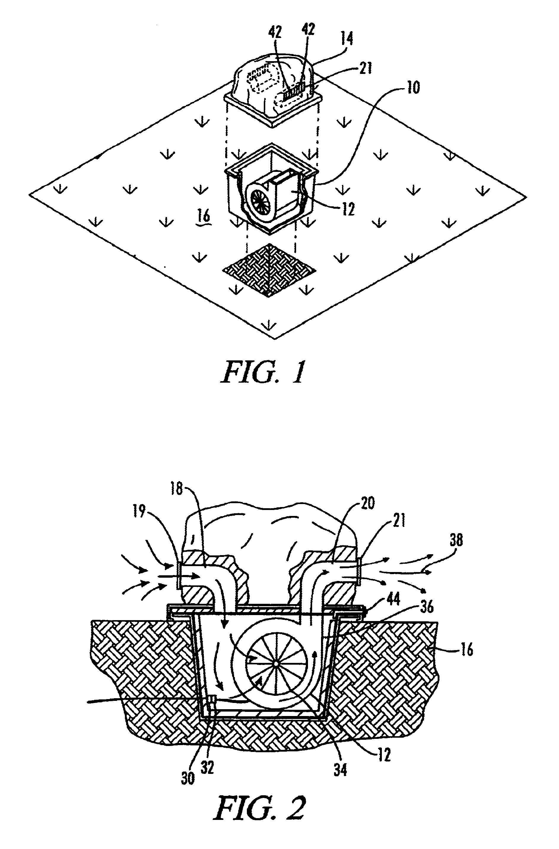
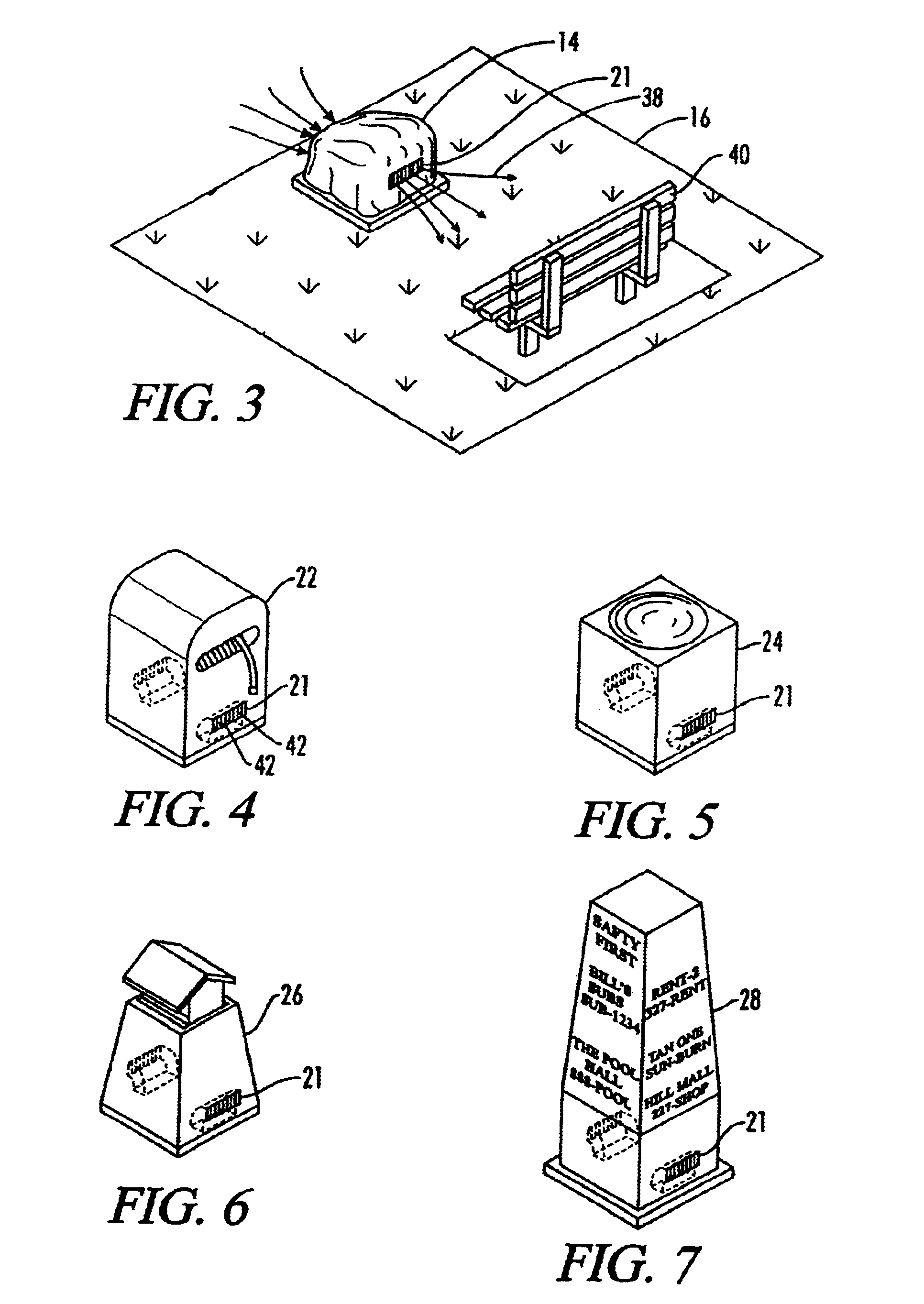
[0057]Referring to FIGS. 1-3, the present invention includes a housing 10, a variable speed fan 12 positioned inside the housing 10, and a rock-shaped lid 14 removably connected to the housing 10. The housing 10 is buried in the ground 16 and provides support for the fan 12. The housing 10 is soundproof, in order to reduce the noise generated by the fan 12, and water resistant, to reduce the amount of water entering the housing 10 from the ground 16. In addition, the housing 10 is ultraviolet (UV) resistant and mildew resistant as well.
[0058]The rock-shaped lid 14 includes a lid air inlet port 18, which allows air to be drawn into the housing 10 by the fan 12, and a lid air outlet port 20, which allows air to be blown out of the housing 10 by the fan 12. In addition, the lid 14 includes a bug screen 19 connected over the lid air inlet port 18 and a diffuser grill 21 connected over the lid air outlet port 20. The bug screen 19 prevents bugs from being drawn into the housing 10 and th...
embodiment 200
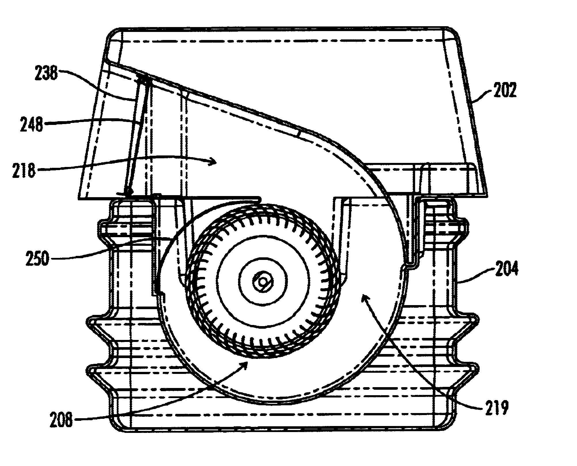
[0073]The dc power source 102 may be inserted into the housing of a particular embodiment and used for applications where an ac power source is not easily available or as a back-up power source for an ac power source. In a similar manner, solar cells 104 may be connected to the lid or housing of a particular embodiment and used to supply power to the invention. Finally, the remote control system 106 may be inserted into the housing or lid and used to remotely control all the functions of the present invention. Referring to FIG. 26, an additional embodiment 200 of the present invention includes an upper housing 202, a lower housing 204, a filter assembly 206, and a fan assembly 208. The fan assembly 206 is designed to be placed inside the lower housing 204, the filter assembly 206 is designed to be connected to the lower housing 204 after the fan assembly 208 has been inserted, and the upper housing 202 is designed to be connected to the lower housing 204 after the filter assembly 20...
PUM
| Property | Measurement | Unit |
|---|---|---|
| Length | aaaaa | aaaaa |
| Flow rate | aaaaa | aaaaa |
| Width | aaaaa | aaaaa |
Abstract
Description
Claims
Application Information