Differential mechanism for a vehicle

a technology of differential gearing and vehicle, which is applied in the direction of differential gearings, mechanical devices, gearings, etc., can solve the problems of not being able to withstand the durability testing, the housing will not be as effective in rear wheel drive vehicles, and the cost of a typical vehicle transmission, so as to increase the torque, increase the torque of the typical transmission, and increase the torque

Active Publication Date: 2005-09-20
RONJO
View PDF14 Cites 46 Cited by
  • Summary
  • Abstract
  • Description
  • Claims
  • Application Information

AI Technical Summary

Benefits of technology

[0007]The inventive configuration of the annular inner surface of the housing portion provides benefits not heretofore provided by prior art differential housings. Unlike differential housings formed from castings, the side bevel gears and the bevel pinion assembly can be inserted mechanically and do not require manipulation into openings typically disposed in cast differential housings. In fact, unlike cast differential housings, each bevel pinion assembly is pre-assembled prior to insertion into the differential housing. Still further, because the housing portion of the differential housing includes an annular wall, more than one bevel pinion assembly can be included in the differential mechanism, which can provide benefits such as, for example, increased torque. It is believed, that by adding two bevel pinion assemblies for a total of four pinion gears, the torque produced by a typical trans

Problems solved by technology

Furthermore, many of the manufacturing drawbacks of cast differential housings have resulted in excessive cost of a typical vehicle transmission.
While the housing formed by the process disclosed in these prior references are believed to be effective for use in a front wheel drive transmission, it is believed that the housings will not be as effectiv

Method used


Image

  • Differential mechanism for a vehicle
  • Differential mechanism for a vehicle
  • Differential mechanism for a vehicle

Examples


Embodiment Construction

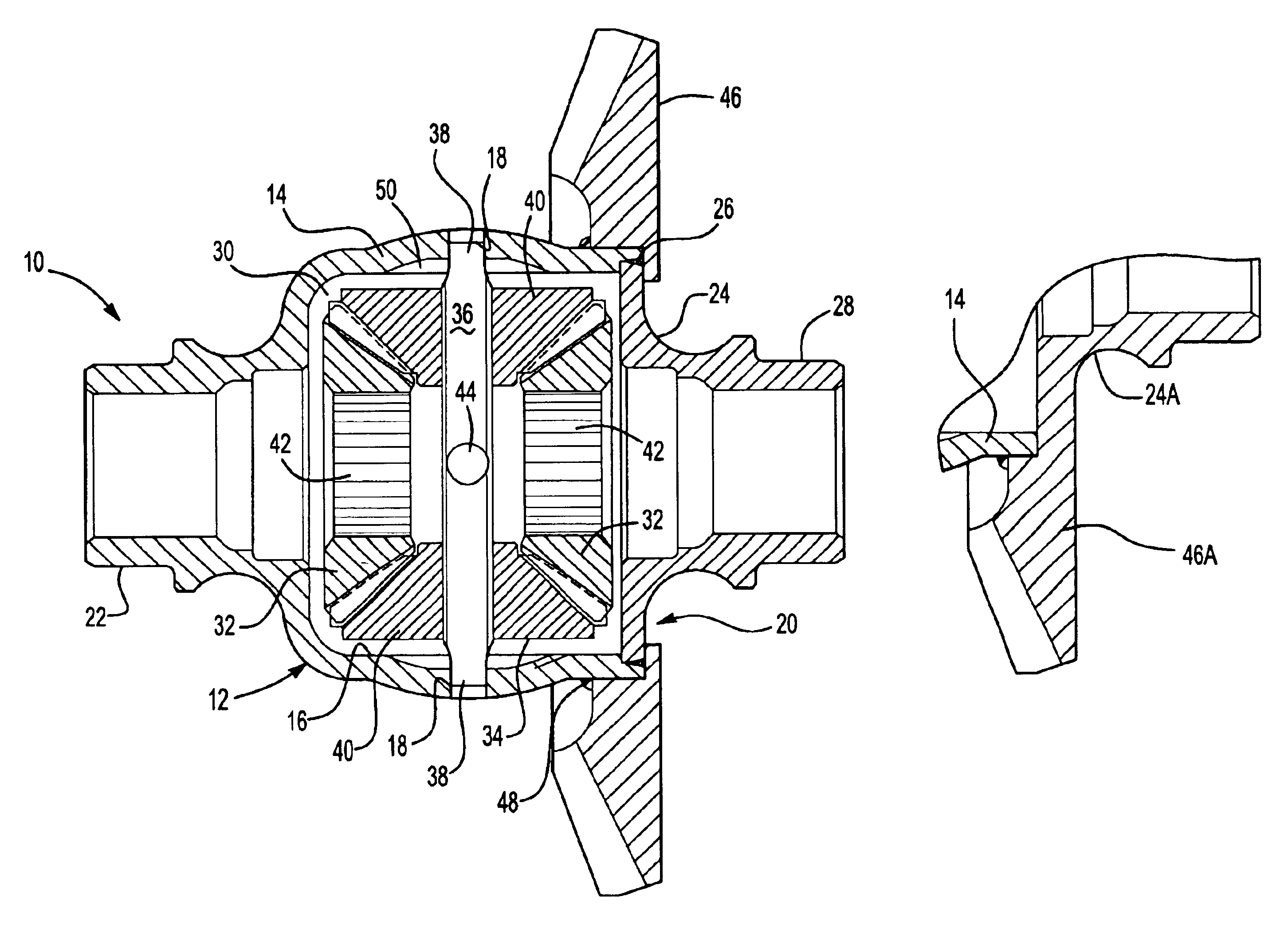
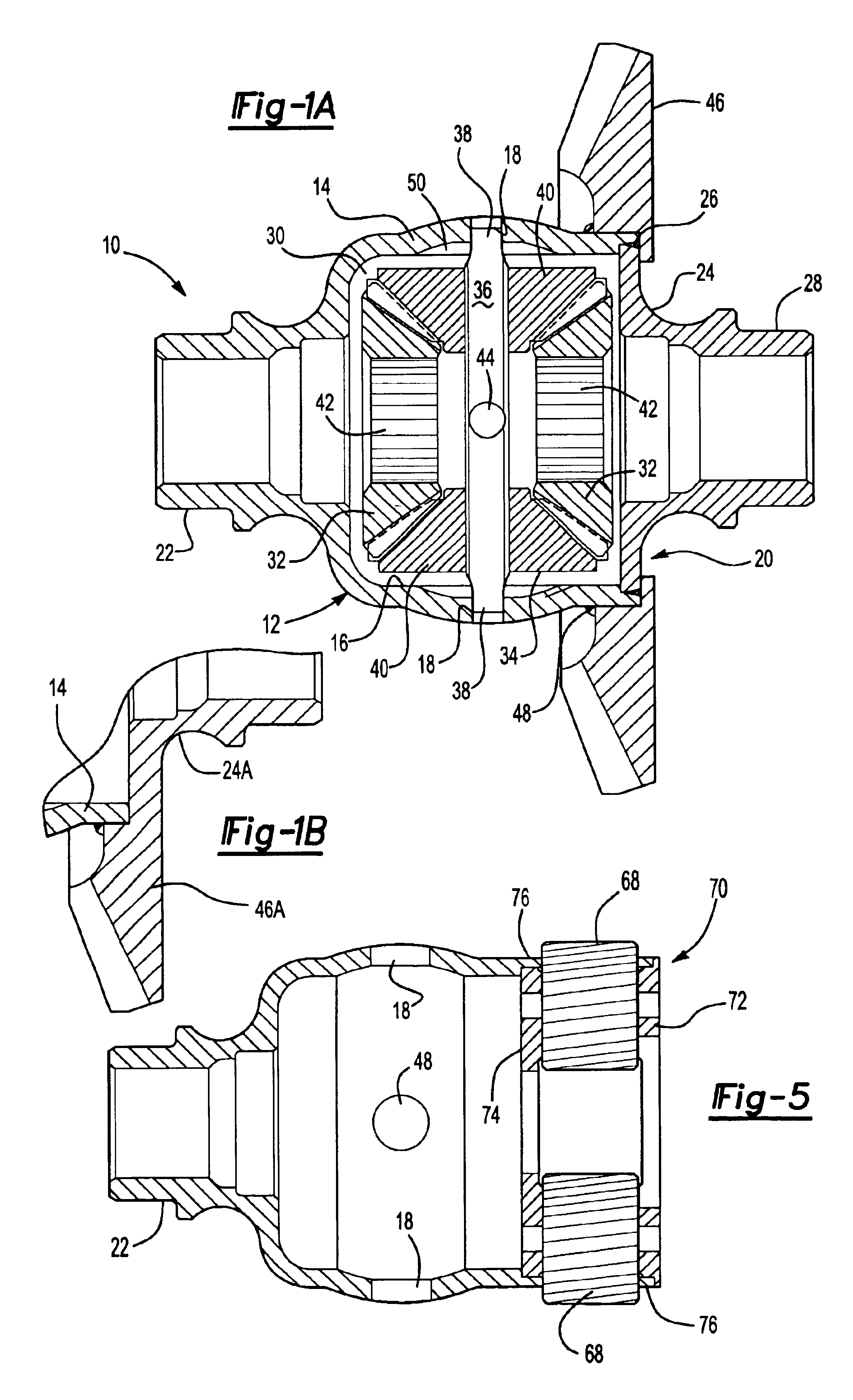
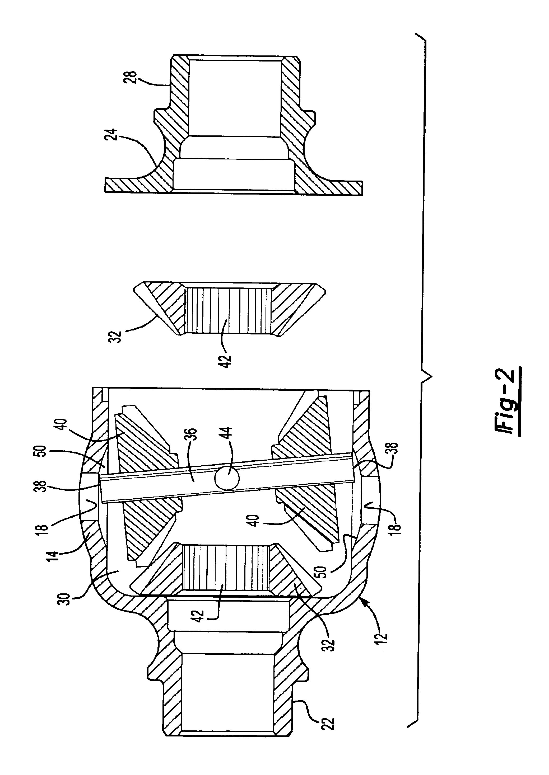
[0019]Referring to FIG. 1, a differential assembly of the present invention is generally shown at 10. A differential housing 12 includes a generally annual wall 14 that defines a generally annular inner surface 16. The inner surface 16 defines at least two receptors 18, and more preferably at least four receptors 18, the purpose of which will be explained further below. The annular wall 14 of the differential housing 12 defines an open end 20. The differential housing 12 defines a journal 22 at an opposite end of the housing 12 from the open end 20. The journal 22 may be formed apart from the housing 12 and then welded to the housing assembly, or may be formed integrally with the housing 12.

[0020]The housing 12 is formed by a spin-forming or flow-forming cold working operation that is particularly suited to produce bowl-shaped parts, and more particularly suited to form rotatably symmetrical parts. The housing 12 is formed over a chuck (not shown) by spinning rollers (not shown) tha...


PUM


Abstract

A differential mechanism includes a housing portion having a generally annular wall with a generally annular inner surface. The annular wall defines an open end of the housing portion. The lid is affixed to the open end forming an enclosure with the housing portion. The opposing side bevel gears are in driving engagement with at least one bevel pinion assembly. The bevel pinion assembly includes at least one bevel pinion shaft with opposing axial ends, each supporting a side bevel gear. The bevel pinion assembly and the side bevel gears are disposed within said enclosure. The annular inner surface defines at least two receptors having ingress's, each receptorengaging one axial end of the pinion shaft independently of the lid.

Description

[0001]This application claims priority to U.S. Provisional Patent Application Nos. 60 / 431,002 filed Dec. 5, 2002 and 60 / 512,001 filed Oct. 16, 2003.FIELD OF THE INVENTION[0002]This invention relates generally to a differential mechanism for use with a vehicle transmission.BACKGROUND OF THE INVENTION[0003]Differential mechanisms are included in vehicle transmissions to transmit torque from a transmission output to opposing axle shafts allowing right and left wheels to rotate at different speeds, particularly important when negotiating a turn. While performing generally the same function, differential mechanisms have different dimensional requirements for rear wheel and front wheel drive vehicles. Specifically, differentials intended for use on front wheel drive vehicles require a beveled, and even annular shape in order to compensate for both the smaller packaging area available and to account for the steering characteristics of the front wheels of the vehicle. Rear wheel drive vehic...

Claims


Application Information

Patent Timeline
IPC IPC(8): F16H48/00F16H48/08F16H48/38F16H48/40F16H57/04
CPCF16H48/08F16H57/04F16H48/40F16H2048/085F16H2048/382F16H2048/385
Inventor SZUBA, JOSEPH
Owner RONJO
Why Eureka
Try Eureka