
Method for producing a thin film comprising introduction of gaseous species

a technology of gaseous species and thin film, which is applied in the direction of solid-state device manufacturing, electric devices, semiconductor/solid-state device manufacturing, etc., can solve the problems of limiting the thickness of the available thickness, causing disturbance, and supplementary presenting drawbacks

Inactive Publication Date: 2005-09-20
COMMISSARIAT A LENERGIE ATOMIQUE ET AUX ENERGIES ALTERNATIVES
View PDF22 Cites 246 Cited by
  • Summary
  • Abstract
  • Description
  • Claims
  • Application Information

AI Technical Summary

Benefits of technology

The present invention proposes a method for making a thin layer from a structure by introducing gaseous species to create an embrittled zone leading to a separation of the structure at the level of the embrittled zone. The method involves making a stacked structure with a first part designed to facilitate the introduction of gaseous species and a second part, the second part having a first free face and a second face integral with the first part. The gaseous species are introduced into the structure from the first part to create an embrittled zone, and the thin layer is then separated from the remaining of the structure at the level of the embrittled zone. The introduction of gaseous species may create an embrittled zone in the first part, in the second part, or at the interface between the first part and the second part. The first part may include a material of high porosity or low stopping power in respect of gaseous species or of thickness corresponding to the depth of penetration of the gaseous species into this first part. The introduction of gaseous species may be carried out by ion implantation through the free face of the first part. The first part may be a self supporting film initially laid on a support, the second part being formed on the first part by growth to provide a manipulable structure. The gaseous species may be selected from among hydrogen and rare gases, these species being able to be introduced alone or in combination.

Problems solved by technology

The entry of these ions may produce disturbance for certain applications.
Obtaining relatively thick films (50 μm for example) requires very powerful implanters, a fact which sets a limit in respect of the thicknesses available.
It may additionally present a drawback in the sense that the thin film obtained has been passed through by the ions intended to form the microcavities.

Method used


Image

  • Method for producing a thin film comprising introduction of gaseous species
  • Method for producing a thin film comprising introduction of gaseous species
  • Method for producing a thin film comprising introduction of gaseous species

Examples


Embodiment Construction

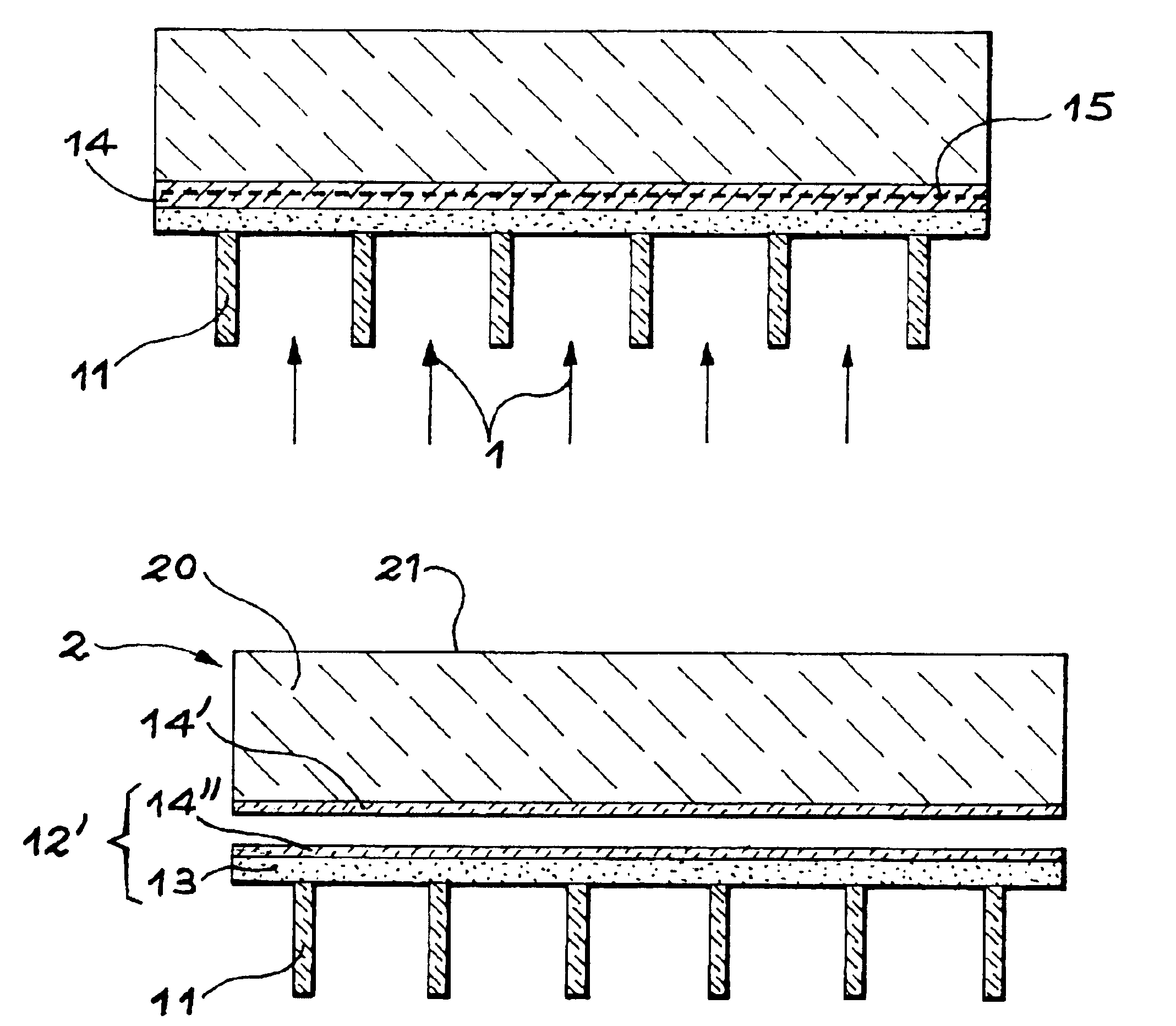
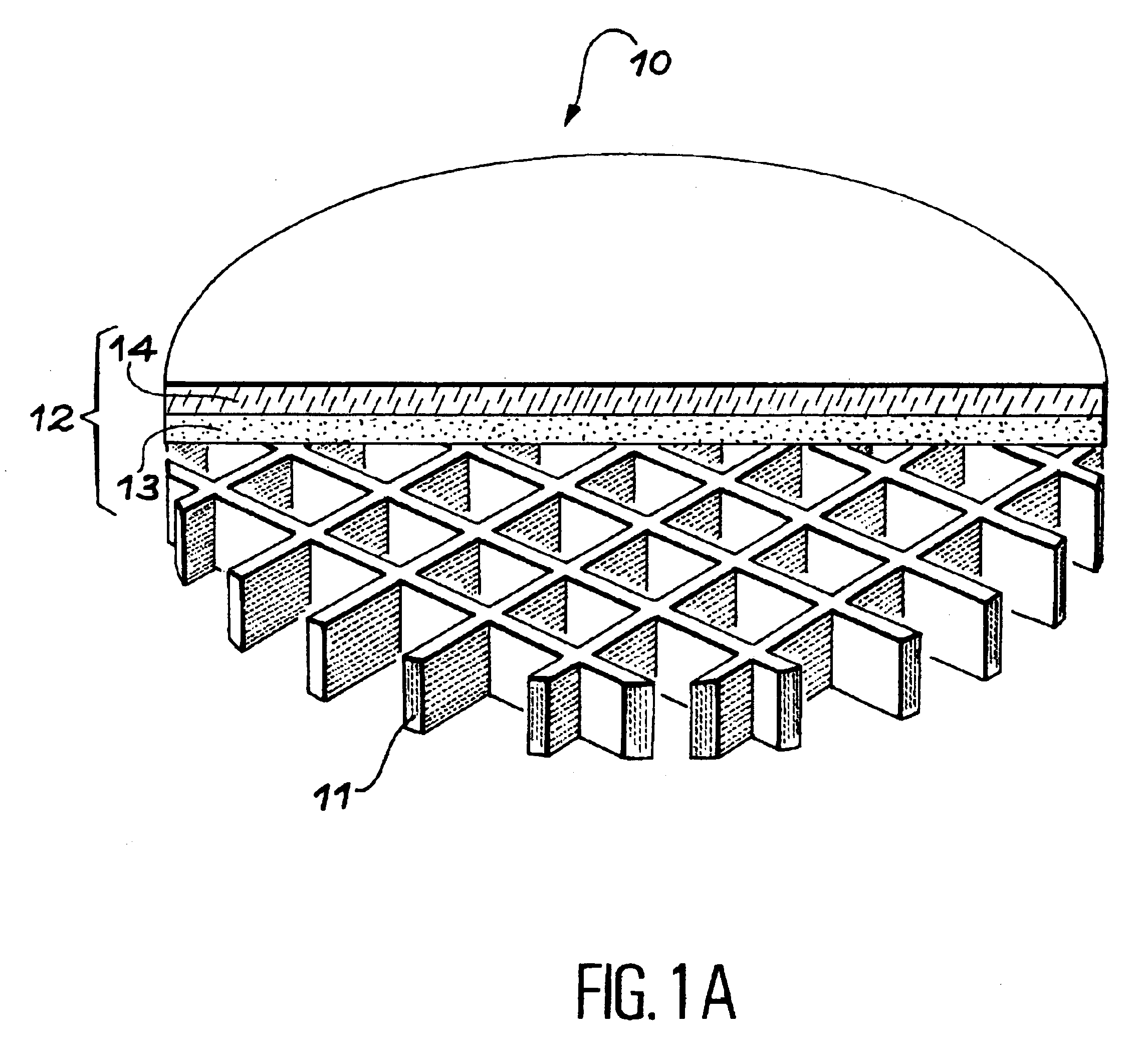
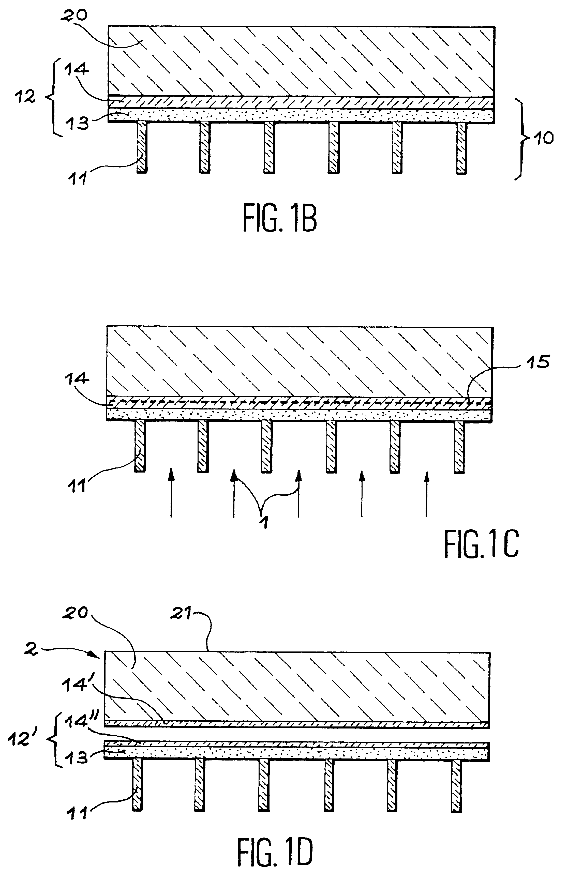
[0025]FIGS. 1A to 1D show an embodiment of the invention wherein the first part of the structure includes a grid.

[0026]FIG. 1A is a perspective and partial cross-section view of this first part 10. The first part 10 includes a grid 11 formed of bars which may be square or rectangular in cross-section. The bars are for example 80 μm wide and may be spaced out from a few hundreds of micrometers to a few millimeters. According to the dimensions of the bars and of the spacings which separate them, the grid may act as a stiffener and allow separation at the level of the implanted zone without inducing the formation of blisters.

[0027]When the spacings between the bars are too big and / or if the depth of penetration of the ions is not sufficient to induce a separation (blistering then occurs) and produce a self supporting film, after the implantation step a layer may be deposited which acts as a stiffener on the free face of the first part.

[0028]The grid 11 may be made by etching a Si or Si...


PUM

PropertyMeasurementUnit
thicknessesaaaaaaaaaa
thickaaaaaaaaaa
thickaaaaaaaaaa

Abstract

A method for making a thin layer from a structure. A stacked structure is made of a first part designed to facilitate the introduction of gaseous species and of a second part, the second part having a first free face and a second face integral with the first part. A gaseous species is introduced into the structure, from the first part, to create an embrittled zone, a thin layer being thus delimited between the first face of the second part and the embrittled zone. The thin layer is separated from the remaining of the structure at the level of the embrittled zone.

Description

TECHNICAL FIELD[0001]The present invention concerns a method for making a thin layer involving the introduction of gaseous species. It allows in particular layers of relatively significant thickness to be made. It finds applications particularly in the field of semi-conductors.STATE OF THE PRIOR ART[0002]The introduction of gaseous species into a solid material may be advantageously achieved by ion implantation. Thus, the document FR-A-2 681 472 (corresponding to U.S. Pat. No. 5,374,564) describes a method for manufacturing thin films of semi-conductor material. This document discloses that the implantation of a rare gas and / or of hydrogen into a substrate made of a semi-conductor material is likely to induce, in certain conditions, the formation of microcavities or platelets to a depth close to the average depth of penetration of the implanted ions. If this substrate is brought into intimate contact, by its implanted face, with a stiffener and a heat treatment is applied at suffici...

Claims


Application Information

Patent Timeline
Patent Type & Authority Patents(United States)
IPC IPC(8): H01L21/70H01L21/762H01L21/02H01L21/301H01L21/265H01L27/12
CPCH01L21/76254H01L21/265
Inventor ASPAR, BERNARDBRUEL, MICHEL
Owner COMMISSARIAT A LENERGIE ATOMIQUE ET AUX ENERGIES ALTERNATIVES
Learn More