Impedance matching device provided with reactance-impedance table

a technology of reactance and impedance table, applied in the field of impedance matching device, can solve the problem that the theoretical value obtained often fails to reflect the actual value of the output impedance zo

Inactive Publication Date: 2005-09-20
DAIHEN CORP
View PDF13 Cites 213 Cited by
  • Summary
  • Abstract
  • Description
  • Claims
  • Application Information

AI Technical Summary

Benefits of technology

[0016]The present invention has been proposed under the circumstances described above. It is, therefore, an object of the present in...

Problems solved by technology

However, the obtained theoretical value often fail...

Method used


Image

  • Impedance matching device provided with reactance-impedance table
  • Impedance matching device provided with reactance-impedance table
  • Impedance matching device provided with reactance-impedance table

Examples


first embodiment

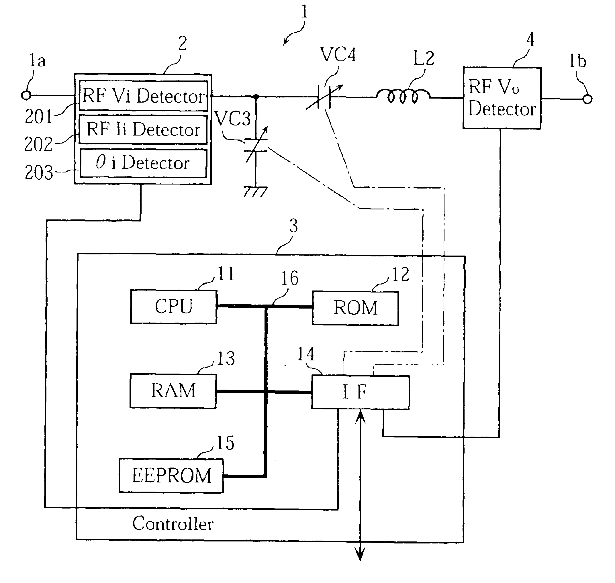
[0071]FIG. 1 is a circuit diagram showing the principal components of an impedance matching device 1 according to the present invention. The impedance matching device 1 includes an input terminal 1a connected to a high-frequency power source (not shown) and an output terminal 1b connected to a plasma chamber (not shown). The device 1 is provided for matching the impedance Zg of the power source and the impedance Zl of the plasma chamber.

[0072]As shown in FIG. 1, the impedance matching device 1 is provided with a multitasking detector 2 connected to the input terminal 1a, a controller 3, an RF voltage detector 4 connected to the output terminal 1b, an inductor L2, and variable capacitors VC3, VC4 (serving as variable reactance elements). The inductor L2 and the capacitors VC3, VC4 constitute a reactance circuit (or matching circuit) of the present invention.

[0073]The controller 3 controls the overall operation of the impedance matching device 1. The controller 3, including a CPU 11, ...

third embodiment

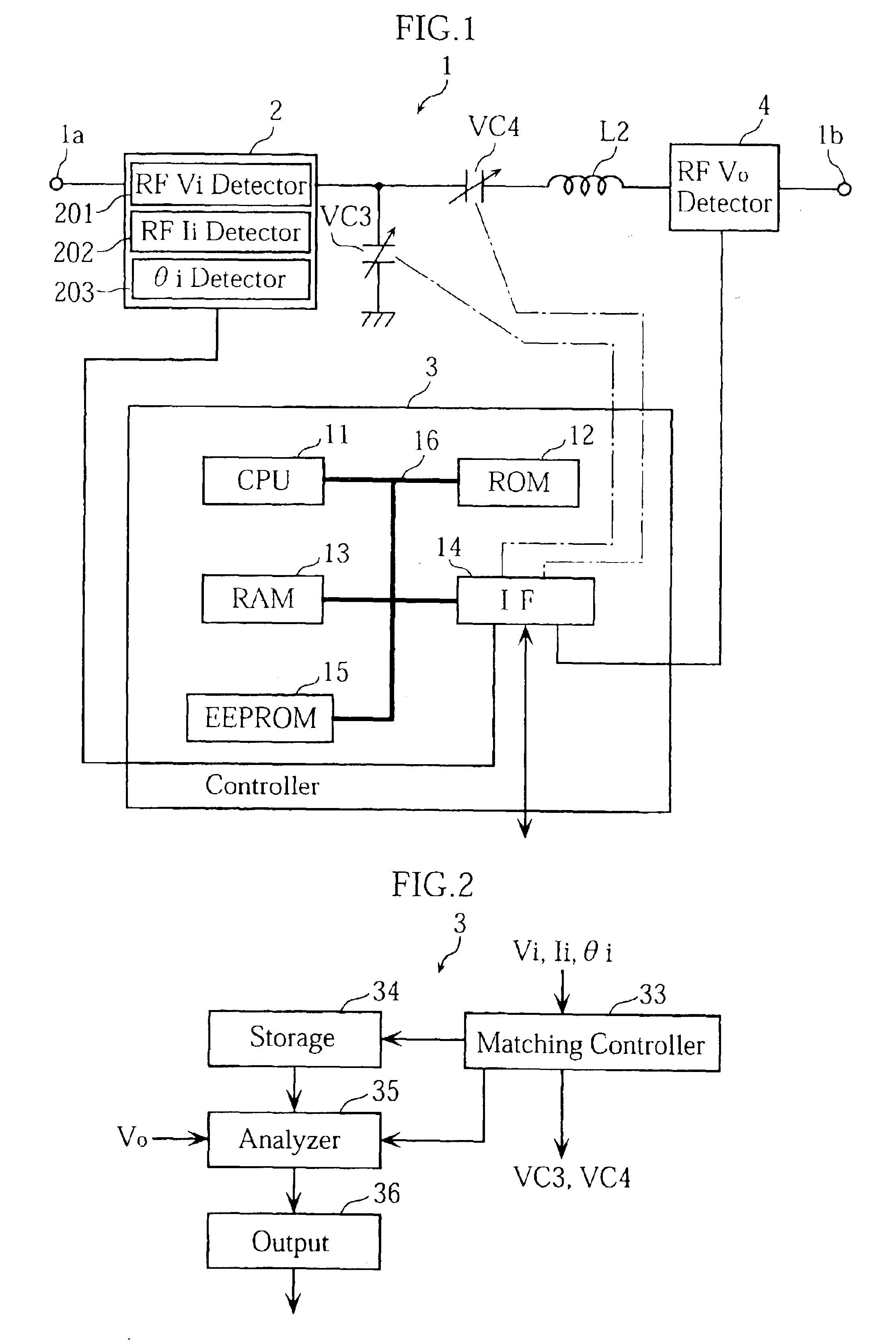
[0132]FIG. 13 is a functional block diagram showing the controller 3 of the impedance matching device according to the present invention. In this embodiment, the capacitance-impedance table is not stored in the impedance matching device, but supplied from outside when the required analysis of the electric characteristics is performed.

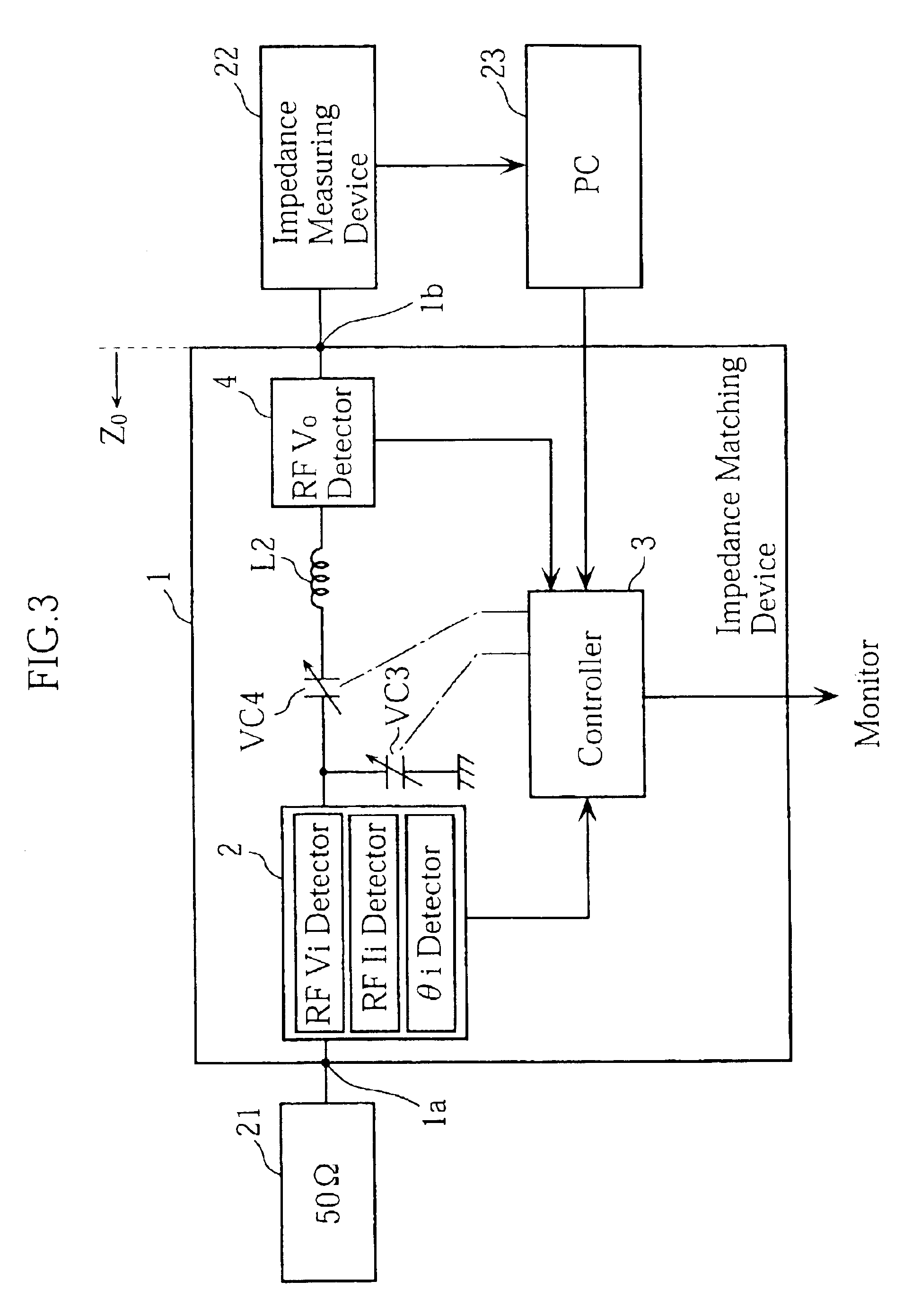
[0133]Specifically, the pre-obtained capacitance-impedance table is stored in the RAM 231 of the external computer 2. Although not shown in FIG. 13, the computer 23 is connected to the controller 3 through the interface 14. When the matching process by the matching control section 33 is completed, the capacitance-impedance table is sent to the analysis section 38 from the computer 23. Based on the table, the detected RF voltage Vo and the adjusted capacitances C3, C4, required calculations are performed to produce the data on the electric characteristics such as the impedance Zl of the chamber 32, the RF current Io at the output terminal 1b and the phas...


PUM


Abstract

An impedance matching device is provided, for which the electric characteristics at an output terminal are accurately analyzed. The matching device is provided with an input detector for detecting RF voltage and current at the input terminal, and an output detector for detecting RF voltage outputted from the output terminal. The matching device also includes a controller for achieving impedance matching between a high frequency power source connected to the input terminal and a load connected to the output terminal. The impedance matching is performed by adjusting variable capacitors based on the detection data supplied from the input detector. When the impedance of the power source is matched to that of the load, the controller calculates the output impedance, RF voltage and RF current at the output terminal, based on the adjusted capacitances of the capacitors, a pre-obtained reactance-impedance data and the detection data supplied from the output detector.

Description

BACKGROUND OF THE INVENTION[0001]1. Field of the Invention[0002]The present invention relates to an impedance matching device used between a high frequency power source and a load. The present invention also relates to a method and a system for analyzing the electric characteristics at an output terminal of an impedance matching device.[0003]2. Description of the Related Art[0004]One of the most important processes performed in producing semiconductor devices or flat panel displays is plasma processing. For generating plasma, a high frequency voltage (RF voltage) of about 100 kHz˜300 MHz is applied to a specially designed plasma chamber.[0005]To maximize the power supply to the plasma chamber, it is necessary to match the impedance of the power source and the impedance of the plasma chamber (“load impedance”), so that the reflection power from the chamber to the power source is minimized. To this end, as shown in FIG. 25, use may be made of an impedance matching device 53 arranged b...

Claims


Application Information

Patent Timeline
IPC IPC(8): H03H11/02H03H11/30
CPCH03H11/30
Inventor NISHIMORI, YASUHIROOMAE, SHUJIMITO, MASAKATSUISHIDA, YUJIITADANI, KOJI
Owner DAIHEN CORP
Why Eureka
Try Eureka