Systems and methods for wirelessly transmitting data from a utility meter

a utility meter and wireless transmission technology, applied in the field of electric utility meters, can solve the problems of uneconomic widespread development of amr systems, and one such cost is associated with the transfer of data using wireless carrier services, and achieve the effect of reducing the airtime cost of transmission

Inactive Publication Date: 2005-09-20
ITRON +1
View PDF42 Cites 94 Cited by
  • Summary
  • Abstract
  • Description
  • Claims
  • Application Information

AI Technical Summary

Benefits of technology

[0004]The present invention is generally directed to a method for wirelessly transmitting data from an utility meter, such as an electric meter. A microprocessor housed inside an energy meter obtains readings of various power indicia, stores the readings, processes the buffer to determine an efficient means of formatting the data for transmission using a radio frequency communications link. The method examines the plurality of readings and determines if values can be communicated by transmitting an initial reading and followed by the difference of the next reading from the previous reading. A special indicator is transmitted to turn ‘on’ compression and allow the receiver to propertly interpret received data. Other indicators are transmitted to turn ‘off’ compression, turn on compression for a pre-defined limited duration, or vary the range of the difference between readings. In one aspect of the invention, an interface board is provided for connecting an electrical power usage meter to a pager board capable of transmitting data to a remote host computer. The interface board includes an input port for connection to the meter for periodically reading load profile data from the meter; and an output port for connection to the pager board for outputting load profile data to the pager board. The load profile data may be transmitted via the pager board and a pager system to a remote host computer. A compact, efficient differential compression method is provided in the interface board to reduce the airtime cost of transmission of load profile data.

Problems solved by technology

Although collection of meter data by wired and wireless networks has been proposed and such meters generally include ports for connectors other than the optical port that could be used by automated meter reading (“AMR”) systems, the widespread development of AMR systems has been uneconomic due to either high equipment costs or significant usage costs when compared to the generally low value of meter readings.
One such cost is associated with transfer of data using wireless carrier services, such as paging service providers.

Method used


Image

  • Systems and methods for wirelessly transmitting data from a utility meter
  • Systems and methods for wirelessly transmitting data from a utility meter
  • Systems and methods for wirelessly transmitting data from a utility meter

Examples


first embodiment

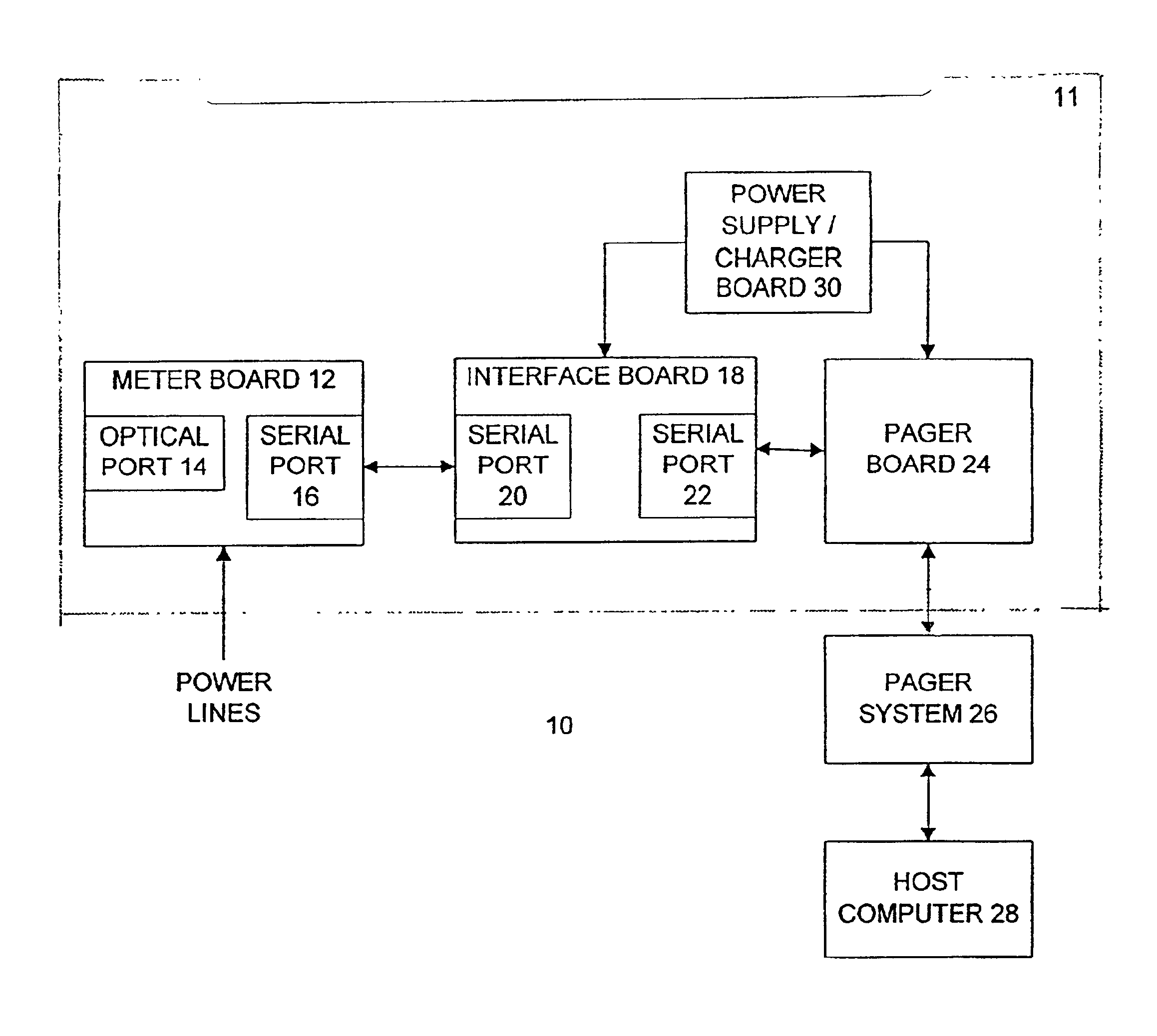
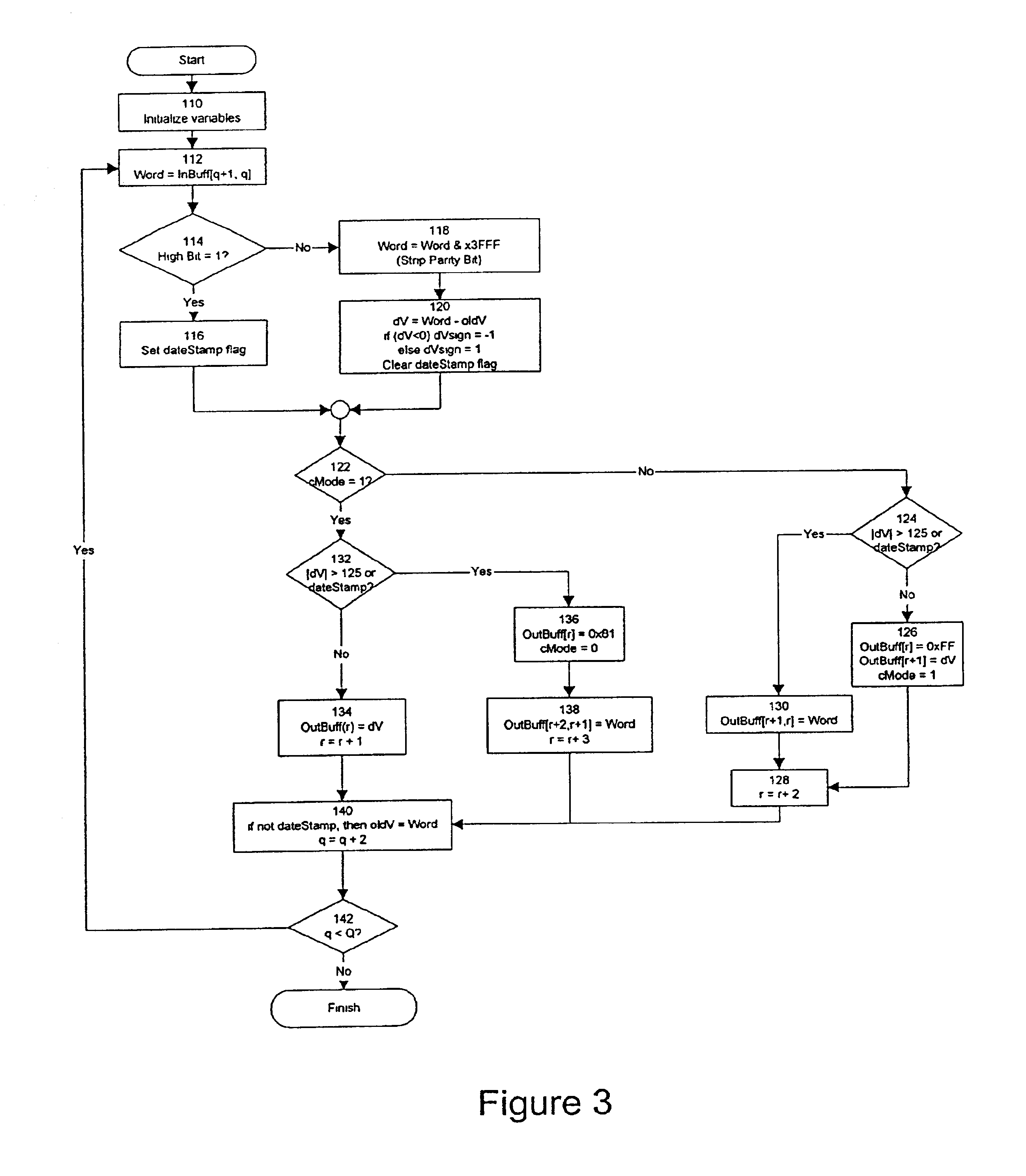
[0047]In the differential compression in the present invention, compression may turned on and off as the stream of raw data words are read from the input buffer by examining the data value of the current word to determine whether the difference between it and the data value of the last data word read can be represented by a single byte. A indicator in the form of a special byte value may be sent to indicate to the host computer 28 signifying that compression is turned on for succeeding bytes until turned off. If compression is on, then to indicate that compression will be off for successive data, a special byte value is used. Since one byte is used to indicate compression will be turned off, the other byte indicates a difference value. This can represent 255 possible values (0x00 to 0xFF provides 256 possible differences) since one value (−128) is reserved to indicate that compression is turned off. Thus, differences of −127 to +127 can be indicated. When uncompressed values are bei...

third embodiment

[0081]The differential compression process illustrated in FIG. 4 can be further modified inot the present invention by the use range-expansion byte values 126, 127, and −128 to indicate that the next difference value is to be increased in absolute value by 125, 252, or 379, respectively. If that modification is added, then the scan-ahead modification discussed above in relation to FIG. 5 should be expanded to scanning ahead past any Words that could be represented by one of the range-expansion byte values 126, 127, or −128 and a difference value to the first Word in the rest of input buffer that is either a data value that can be represented as a single-byte difference without a range-expansion byte, a data value that cannot be represented as a single-byte difference even with a range-expansion byte, or a time / date stamp. In effect, since data values represented by a range-expansion byte and a difference byte require a two-byte word to transmit, they should be ignored for the purpos...


PUM

PropertyMeasurementUnit
voltageaaaaaaaaaa
voltageaaaaaaaaaa
phase voltageaaaaaaaaaa

Abstract

A method for wirelessly transmitting data from an utility meter, such as an electric meter, is disclosed. A microprocessor housed inside an energy meter obtains readings of various power indicia, stores the readings, processes the buffer to determine an efficient means of formatting the data for transmission using a radio frequency communications link. The method examines the plurality of readings and determines if values can be communicated by transmitting an initial reading and followed by the difference of the next reading from the previous reading. A special indication is transmitted to turn ‘on’ compression and allow the receiver to propertly interpret received data. Other indicators are transmitted to turn ‘off’ compression, turn on compression for a pre-defined limited duration, or vary the range of the difference between readings.

Description

CROSS REFERENCE TO RELATED APPLICATIONS[0001]This application claims the benefit of U.S. Provisional Application No. 60 / 263,768, filed on Jan. 25, 2001, which is incorporated herein by reference.FIELD OF THE INVENTION[0002]The present invention relates generally to electronic utility meters, and more particularly to a method of wirelessly transmitting meter reading data from a utility meter, such as an electric meter, to a central host computer for recording and reporting meter readings. Readings may include scheduled events, such as periodic usage data, or unscheduled events, such as service interruptions.BACKGROUND OF THE INVENTION[0003]Conventional commercial and industrial electronic meters, such as the meter described in U.S. Pat. No. 6,112,159 (“the Siemens S4”), the meter described in U.S. Pat. No. 6,081,204, and the meter described in U.S. Pat. No. 6,094,622, which are all incorporated by reference herein, are primarily designed for reading via an optical port. Although coll...

Claims


Application Information

Patent Timeline
Patent Type & Authority Patents(United States)
IPC IPC(8): G08C17/00G08C17/02
CPCH04Q9/00H04Q2209/60
Inventor MUELLER, WILFREDJOHNSON, RODERICK MICHAELBLACKWELL, DANEHAMILTON, PATRICK C.NEEDHAM, DENNIS M.SCRIBNER, ALLAN L.
Owner ITRON
Why Eureka
Try Eureka