Imaging system for vehicle

a vehicle and imaging system technology, applied in the direction of traffic control systems, navigation instruments, instruments, etc., can solve the problems of low cost, inability to maintain line-of-sight between the vehicle and a sufficient number of satellites, and high cost of gyroscopes and multi-axis accelerometers, so as to achieve low cost and low cost

Inactive Publication Date: 2005-09-20
DONNELLY CORP
View PDF53 Cites 795 Cited by
  • Summary
  • Abstract
  • Description
  • Claims
  • Application Information

AI Technical Summary

Benefits of technology

[0010]Therefore, the present invention provides an imaging system which is operable in connection with a global positioning system of the vehicle and / or a magnetic compass system of the vehicle. The imaging sensor suitable for use with the present invention may be useful in connection with other vehicular systems, functions and / or controls as well. For example, the imaging sensor may be an imaging array sensor useful in connection with a vehicular vision or imaging system, such as a rearward facing vision system, a forward facing vision system, a headlamp control system, a rain sensor system, a lane departure warning system, a traffic sign recognition system, a system for determining a distance to a leading vehicle or object, and / or the like. The imaging system of the present invention thus may provide a low cost means for tracking vehicle position between interrupted satellite signals and / or a low cost means for providing a continuously calibrated compass heading, since the cost associated with the imaging sensor may be spread over or shared by multiple systems or controls of the vehicle.

Problems solved by technology

One problem with global positioning systems is that they rely on an uninterrupted line-of-sight between the vehicle and a required minimum number of the satellites deployed in the particular system.
In many areas or regions, particularly urban areas or regions, the line-of-sight between the vehicle and a sufficient number of satellites is not possible to maintain.
However, such gyroscopes and multi-axis accelerometers are costly and may provide inaccurate data at low speeds.
Also, magnetic compasses are subject to error due to significant ferrous content in the structures common in those areas in which satellite views are restricted.
Additionally, differential compasses may provide erroneous data due to differences in the rolling radii of the vehicle wheels.

Method used


Image

  • Imaging system for vehicle
  • Imaging system for vehicle

Examples


Embodiment Construction

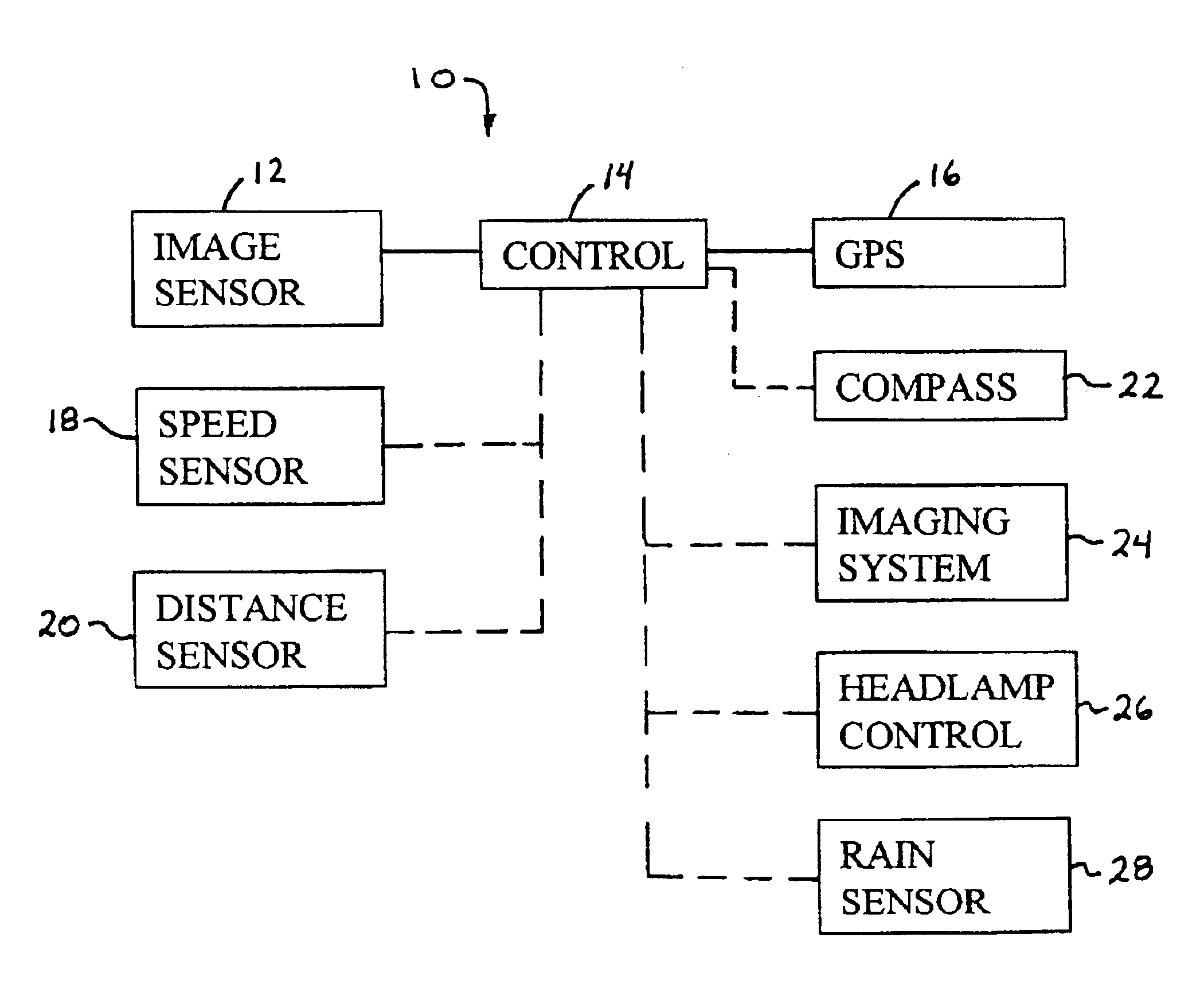
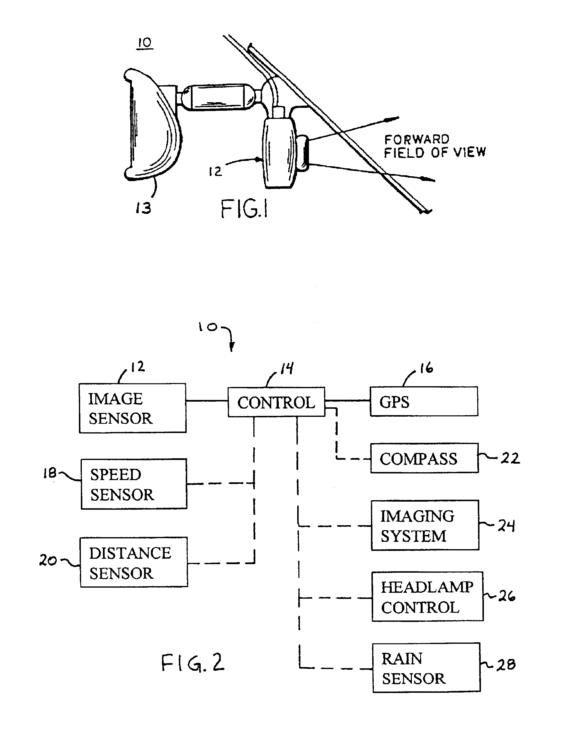
[0014]Referring now to the drawings and the illustrative embodiments depicted therein, an imaging system 10 in accordance with the present invention includes an imaging sensor 12 which is positioned or mounted at a vehicle (FIGS. 1 and 2) and operable to capture an image of a scene occurring exteriorly of the vehicle. As shown in FIG. 1, the imaging sensor 12 may be mounted at an interior rearview mirror 13 at the windshield of the vehicle and may be facing generally forwardly with respect to the direction of travel of the vehicle, such that the imaging sensor may be operable to capture an image of a scene within a field of view forwardly of the vehicle. The imaging system further includes a control or control device 14 (FIG. 2) which is operable in connection with a global positioning system 16 of the vehicle. The control device 14 is operable to track or record movement of the vehicle in response to processing of images or frames captured by the imaging sensor, in order to track t...


PUM


Abstract

An imaging system suitable for use with a vehicle based global positioning system includes an imaging sensor and a control. The imaging sensor is positioned at the vehicle and may face generally forwardly with respect to the direction of travel of the vehicle. The control may be operable to provide a record of vehicle movement since the last position data derived from the vehicle based global positioning system. The imaging system may also or otherwise be suitable for use with a vehicle based magnetic compass system. The imaging system may be operable in combination with a magnetic field sensor of the magnetic compass system to provide a substantially continuously calibrated heading indication, which is substantially resistant to local magnetic anomalies and changes in vehicle inclination. The imaging sensor may be associated with one or more other accessories of the vehicle.

Description

CROSS REFERENCE TO RELATED APPLICATION[0001]The present application claims priority on U.S. provisional application, Ser. No. 60 / 375,523, filed Apr. 25, 2002 by Schofield for IMAGING SYSTEM FOR VEHICLE, which is hereby incorporated herein by reference in its entirety.FIELD OF THE INVENTION[0002]The present invention relates generally to an imaging system for a vehicle and, more particularly, to an imaging array system for use in combination with a global positioning system and / or a magnetic compass system of the vehicle.BACKGROUND OF THE INVENTION[0003]Global positioning systems (GPS) are used in vehicles to determine the current position of the vehicle on the earth's surface. Current position data may be used in applications such as on-board navigation systems, remote navigation, emergency response and concierge service systems, fleet tracking applications, speed restriction violation monitoring for insurance loading purposes, vehicle recovery, and many others. One problem with glo...

Claims


Application Information

Patent Timeline
Patent Type & Authority Patents(United States)
IPC IPC(8): G01C21/10G01C21/00G01C21/16
CPCG01C21/00G01C21/165G01C21/12G01C21/1656G01C21/1654
Inventor SCHOFIELD, KENNETH
Owner DONNELLY CORP
Why Eureka
Try Eureka