Focussing and focal length adjusting device for a video camera

a technology for video cameras and adjusting devices, which is applied in the direction of instruments, television systems, building rescue, etc., can solve the problems of inability to jump-like movement to a certain target position, the nature of the use may not be accepted, and the picture signal is distorted

Inactive Publication Date: 2005-09-20
RICHARD WOLF GMBH
View PDF25 Cites 16 Cited by
  • Summary
  • Abstract
  • Description
  • Claims
  • Application Information

AI Technical Summary

Benefits of technology

[0008]It is the object of the invention to specify a focussing and focal distance adjusting device for an optical lens system of a video camera, in particular for an endoscope, with which neither in the camera head nor in the cable to the camera controller are there caused disturbances of the picture signal. Furthermore as small and as light as possible drive for the focussing device is to be made possible which mi

Problems solved by technology

In endoscopy an autofocus may only be accepted when it reacts unnoticeable to the human eye, from which there results the demand that the used control system as well as the drive must be very quick and that such a drive, neither in the camera head nor in the cable to the camera controller, may cause disturbances of the picture signal.
The use of electric motors in endoscopic camera heads often entails disturbances in the video picture which by way of the nature of the use may not be accepted.
Furthermore electric motors may only be moved successively in one direction, and a jump-like movement to a certain target

Method used


Image

  • Focussing and focal length adjusting device for a video camera
  • Focussing and focal length adjusting device for a video camera
  • Focussing and focal length adjusting device for a video camera

Examples


first embodiment

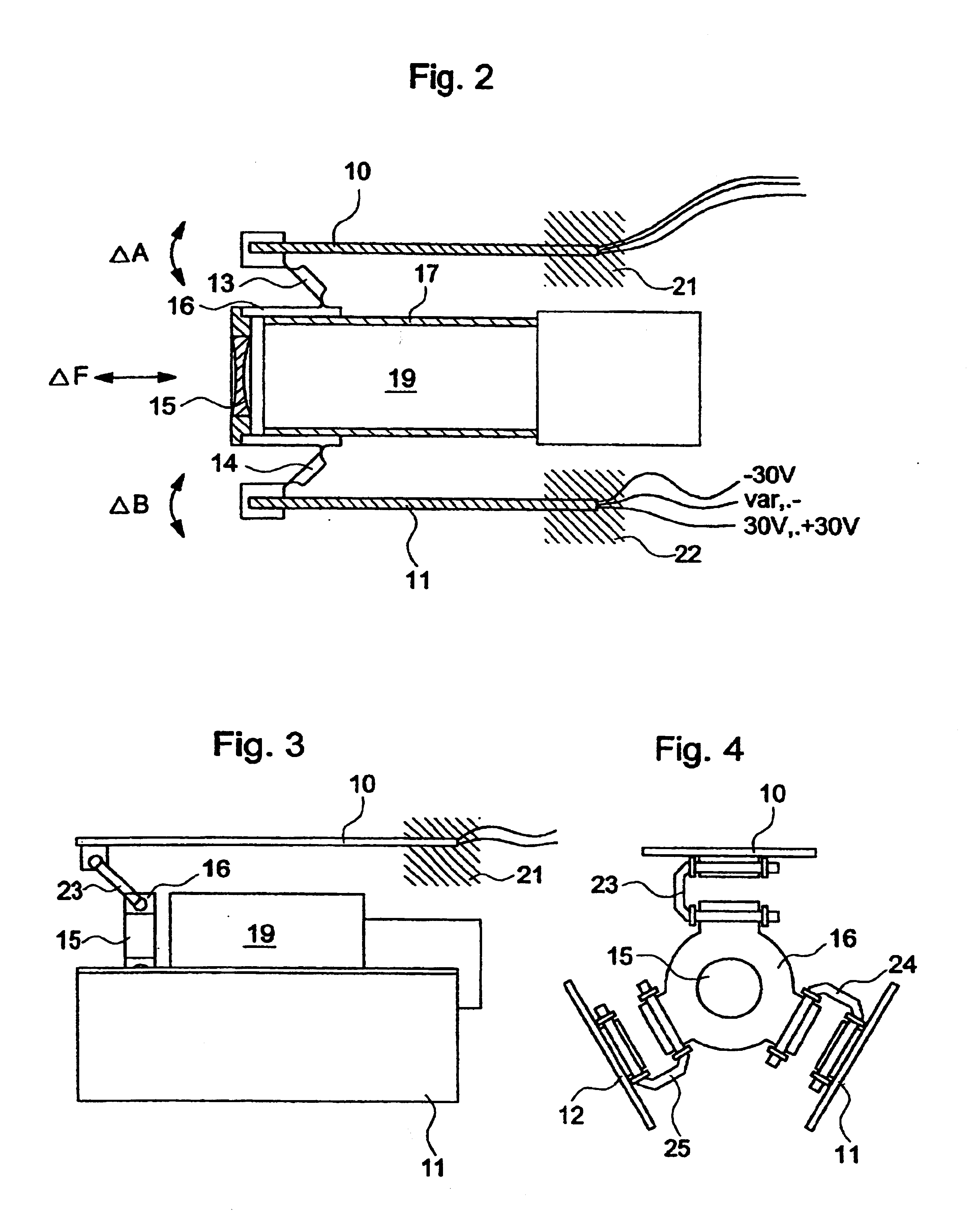
[0022]In FIG. 2 which schematically shows a longitudinal section through a first embodiment using piezoelectric bending actuators, two parallel strip-like elongate piezoelectric bending actuators 10 and 11 are positioned symmetrically to the optical axis of an optical lens system 19 contained in a sleeve 17 and at their one end are fixed for example by molding in (fixing locations 21 and 22). When to these actuators 10, 11 as mentioned above, in the vertical blanking interval, there is supplied an electrical charge, the piezoelectric bending actuators 10, 11 are in the position, in this time interval, to deflect their non-fixed end shown on the left in FIG. 2 (arrows A and B). This deflection is transmitted via in each case one link member 13, 14 to an outer sleeve 16 carrying a focussing lens 15. The direction of the movement which originally ran orthogonally to the optical axis of the system is by way of the inclination of the connection element contained in the joint members 13, ...

second embodiment

[0025]In the FIGS. 3 and 4 which in each case show schematically a longitudinal section and a cross section through a focussing device according to the invention equipped with piezoelectric bending actuators, three piezoelectric bending actuators 10, 11 and 12 are arranged parallel to and symmetrically to the optical axis of the focussing lens 15 in each case angularly displaced by 120°.

[0026]The redirection of the bending movement of the free end of the piezoelectric bending actuator 10, 11 and 12 is effected with this embodiment by the wire joints 23, 24 and 25 which are attached on the circumference of the focussing lens holder 16 at distances of 120°. By way of this type of suspension a linear guiding of the focussing lens 15 according to FIG. 2 may be done away with. Deflection differences of the three actuators 10, 11 and 12 may be compensated by activation.

[0027]It is yet to be mentioned that to the sleeve 17 containing the camera lens system 19 as usual there connects a reco...


PUM


Abstract

A focussing and focal length adjusting device for an optical lens system in the camera head of an endoscope. This device includes a focussing device which has several piezoelectric bending actuators attached along and symmetrically to the optical axis of the focussing lens. The piezoelectric bending actuators are via in each case one joint member connected to a sleeve encompassing the focussing lens in a manner such that with voltage impingement bending movements carried out by the bending actuators are converted into a linear focussing movement for the focussing lens. Furthermore a zoom drive adjusting the focal length of a zoom lens system includes a stepper motor whose stepped rotation via a grooved roller and a pin linearly moved by the helical groove of this roller is converted into a linear movement of a zoom lens sleeve for the focal length adjustment. The activation of the stepper motor for the zoom operation, and the production of the focus adjusting signal for the piezoelectric actuators of the focussing device are effected during the vertical blanking interval of the video signal, this interval being extracted by an extraction circuit from the video signal and being led to a respective focussing circuit and a zoom control circuit in the form of a time window.

Description

BACKGROUND OF THE INVENTION[0001]1. Field of the Invention[0002]The invention relates to a focussing and focal length adjusting device for a video camera, in particular for an optical lens system in an endoscopic video camera, with a drive device moved by at least one piezoelectric actuator, for a focussing lens of the lens system, with an automatic focussing circuit for producing a focus adjusting signal which can be supplied to the piezo electric actuator, and with an electromotoric zoom drive, connected to a zoom objective of the optical lens system, with a zoom control circuit which with a manually inputted zoom signal produces a focal length adjusting signal for the zoom drive.[0003]2. Discussion of the Prior Art[0004]Particularly with endoscopic applications with which the operating surgeon does away with an assistant guiding the camera and holds the camera himself or has it fixed by way of a mechanical holding arm, the automation of the frequent picture focussing readjustment...

Claims


Application Information

Patent Timeline
IPC IPC(8): G02B7/10H04N5/225H04N5/232G02B7/04G02B7/08G02B23/24G02B7/09G02B7/28
CPCG02B7/102H04N5/2251H04N5/23212H04N2005/2255H04N23/555H04N23/50H04N23/67
Inventor WIDMANN, HOLGERVOEGELE, MICHAELOSTERLAND, ULRICH
Owner RICHARD WOLF GMBH
Why Eureka
Try Eureka