Video processing apparatus for converting composite video signals to digital component video signals

a video signal and video signal technology, applied in the field of video signals, can solve problems such as interference signals, beat-like noise on the screen, and difficulty in manufacturing multi-type, digital choroma-decoders on one substrate or one semiconductor chip

Inactive Publication Date: 2005-09-20
SONY CORP
View PDF10 Cites 12 Cited by
  • Summary
  • Abstract
  • Description
  • Claims
  • Application Information

AI Technical Summary

Benefits of technology

[0011]The timing signal is synchronous with a virtual clock signal when its cycle is averaged within a specific period. The signal generated by interpolation has the same frequency as the input signal (i.e., broadcast signal) or the output signal obtained by sampling the broadcast signal. Therefore, the input signal can be digitally processed without troubles, even if the timing signal is not completely synchronous with the virtual clock signal.
[0013]Furthermore, the tap coefficient applied to interpolation can be changed in accordance with the phase difference between the timing signal and the virtual clock signal. This makes it easy to effect the interpolation.

Problems solved by technology

If a plurality of system clocks are mounted on one substrate or one semiconductor chip, however, the system clocks interfere with one another, generating interference signals.
The interference signals enter, for example, the analog input of the A / D converter, inevitably resulting in beat-like noise on the screen.
In view of this, it is very difficult to manufacture a multi-type, digital choroma-decoder on one substrate or one semiconductor chip.

Method used


Image

  • Video processing apparatus for converting composite video signals to digital component video signals
  • Video processing apparatus for converting composite video signals to digital component video signals
  • Video processing apparatus for converting composite video signals to digital component video signals

Examples


Embodiment Construction

[0022]An embodiment of the present invention, or a chroma-decoder, will be described.

[0023]The chroma-decoder is an apparatus that decomposes a composite video signal into a luminance signal and a color-difference signal and generates, from the luminance signal and the color-difference signal, a video signal that has a sampling clock frequency of 13.5-MHz as is defined by the ITU-R601 standard. The composite video signal input to the chroma-decoder complies with any TV broadcasting systems such as NTSC system, PAL system and SECAM system.

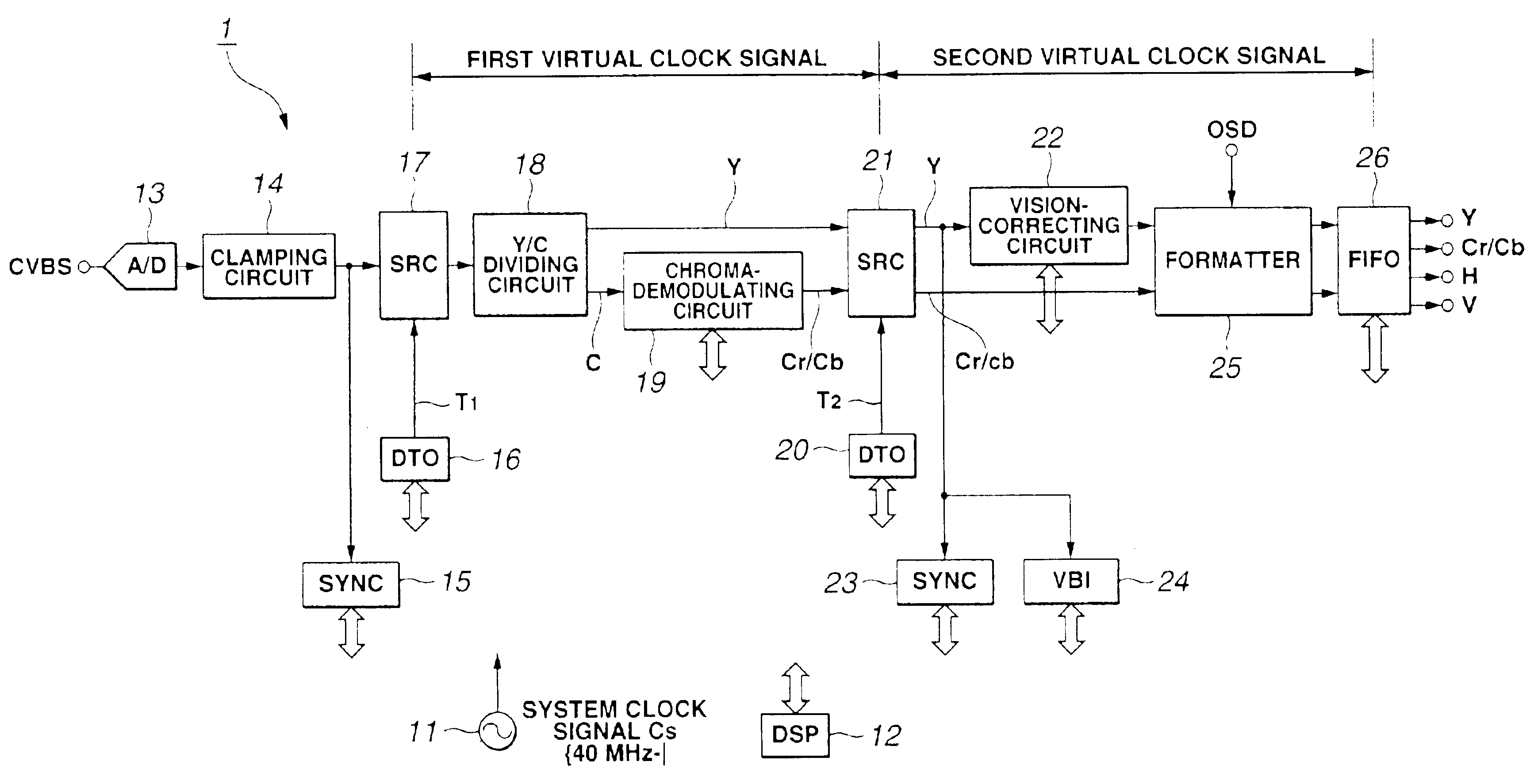
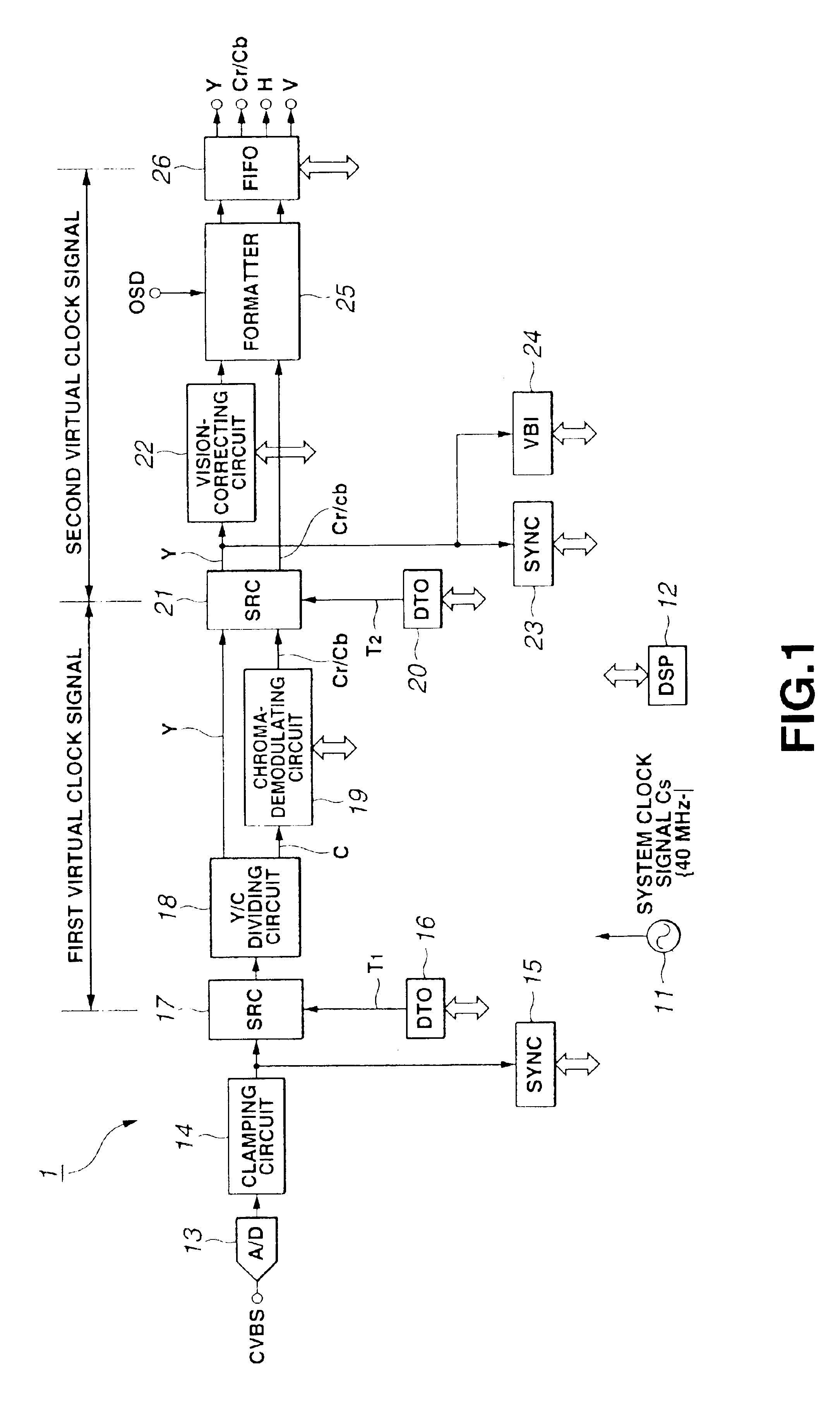
[0024]FIG. 1 is a block diagram of the chroma-decoder 1 according to the present invention.

[0025]As FIG. 1 shows, the chroma-decoder 1 comprises a system-clock oscillator 11, a digital signal processor (DSP) 12, an analog-to-digital (A / D) converter 13, a clamping circuit 14, a synchronous detector (SYNC circuit) 15, a first timing oscillator (DTO) 16, a first sampling-rate converter (SRC) 17, a luminance / chroma dividing circuit (Y / C) 18, a chroma-de...


PUM


Abstract

A chroma-decoder 1 has two SRCs 17 and 21. The first SRC 17 performs down-conversion, changing the sampling rate of a composite video signal sampled with a system clock signal Cs to the sampling rate (14.3 MHz) of an NTSC signal. The signal generated by the SRC 17 is output in synchronism with the system clock signal Cs. The signal is then divided into a luminance signal Y and a color-difference signal C, which are subjected to chroma decoding. The second SRC 21 performs down-conversion, changing the sampling rate of the luminance signal and color-difference signal of the NTSC signal to the sampling rate (13.5 MHz) of an ITU-R601 standard.

Description

BACKGROUND OF THE INVENTION[0001]1. Field of the Invention[0002]The present invention relates to a video signal that performs so-called “chroma-decoding,” thereby to convert composite video signals to digital component signals. More particularly, the invention relates to a video signal processing apparatus that can be used in various broadcasting systems such as NTSC system, PAL system, SECAM system and the like.[0003]2. Description of the Related Art[0004]To output a video signal after receipt of a composite video signal broadcast, the composite video signal is chroma-decoded. More precisely, the composite video signal is decomposed into a luminance signal (Y) and color-difference signals (Cb, Cr). The luminance signal and the color-difference signals constitute a component video signal. The chroma decoding is followed by matrix conversion that converts the component video signal to an RGB signal. The RGB signal is subjected to MPEG encoding. In recent years, a digital circuit perf...

Claims


Application Information

Patent Timeline
Patent Type & Authority Patents(United States)
IPC IPC(8): H04N9/64H04N9/66
CPCH04N9/641
Inventor KUMAZAWA, NAOKI
Owner SONY CORP
Why Eureka
Try Eureka