
Optical phase modulator

a phase modulator and liquid crystal technology, applied in the field of phase modulators, can solve the problems of high cost, heavy correction devices, and inability to provide a maximum phase shift of 360° for phase modulators based on topological phases

Inactive Publication Date: 2005-09-20
DEUTSCHE TELEKOM AG
View PDF4 Cites 9 Cited by
  • Summary
  • Abstract
  • Description
  • Claims
  • Application Information

AI Technical Summary

Benefits of technology

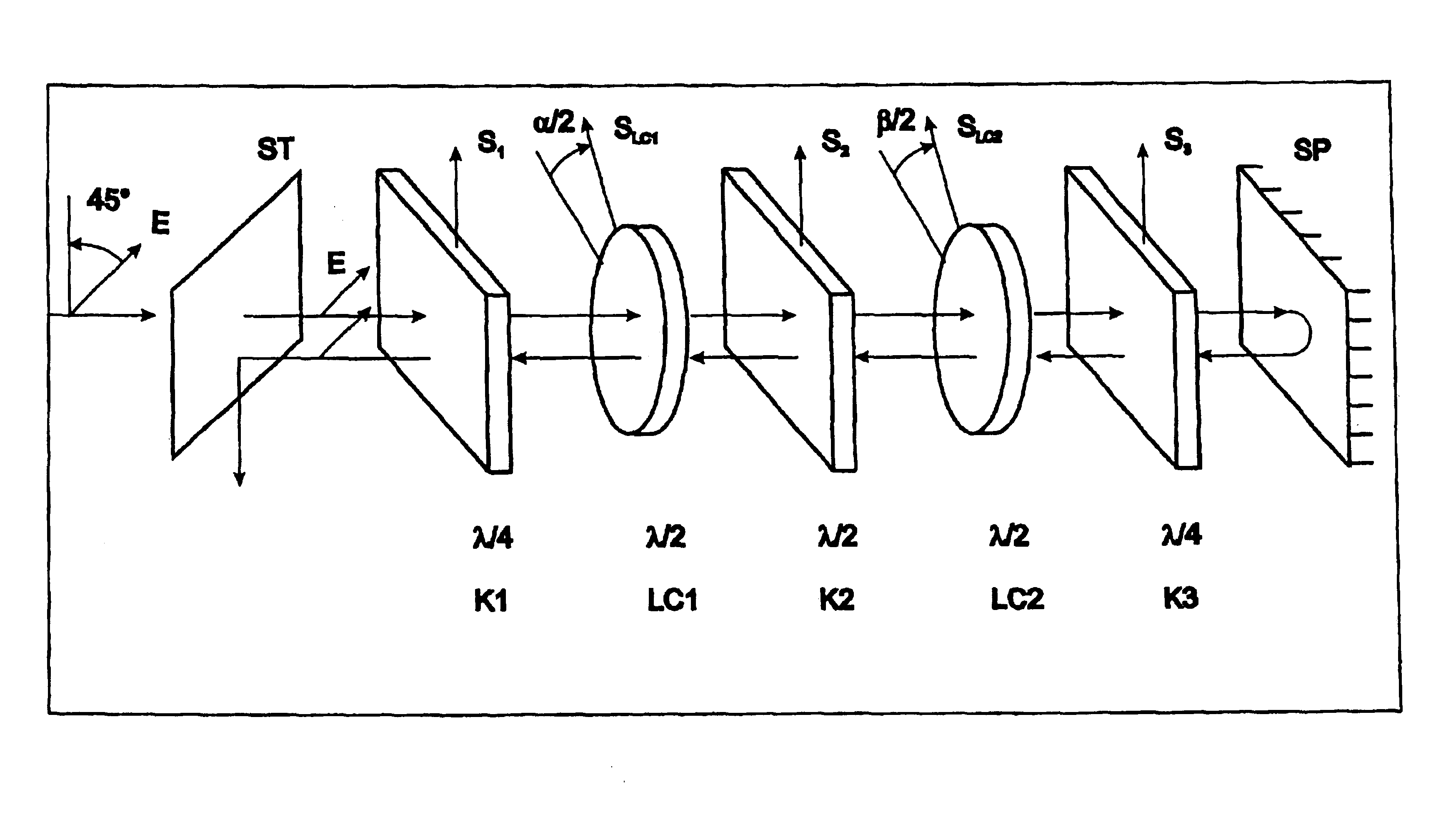
[0010]The phase modulator of the present invention can be able to generate an adjustable phase shift within the range of between 0 and 360°, without the mechanical shift or rotation of optical components, for example by an electrical triggering of the delay element having a rotatable indicatrix.

Problems solved by technology

However, a phase adaptation of this kind entails heavy correction devices, and can be very cost intensive.
Previously available phase modulators having liquid crystals based on the topological phase are not able to provide a maximum phase shift of 360°, as is often required when a phase modulator is provided for the applications mentioned at the outset.

Method used


Image

  • Optical phase modulator
  • Optical phase modulator
  • Optical phase modulator

Examples


Embodiment Construction

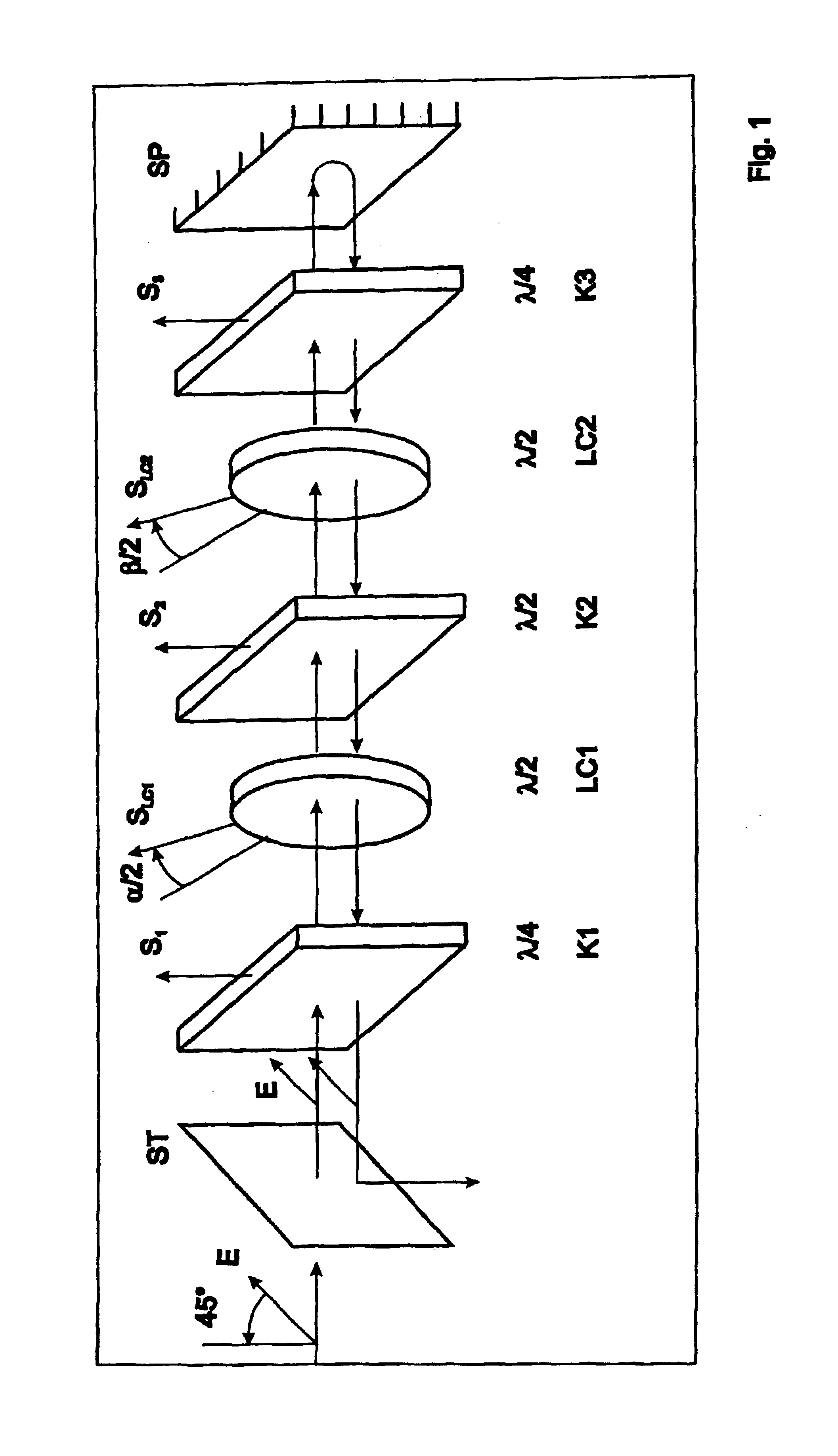
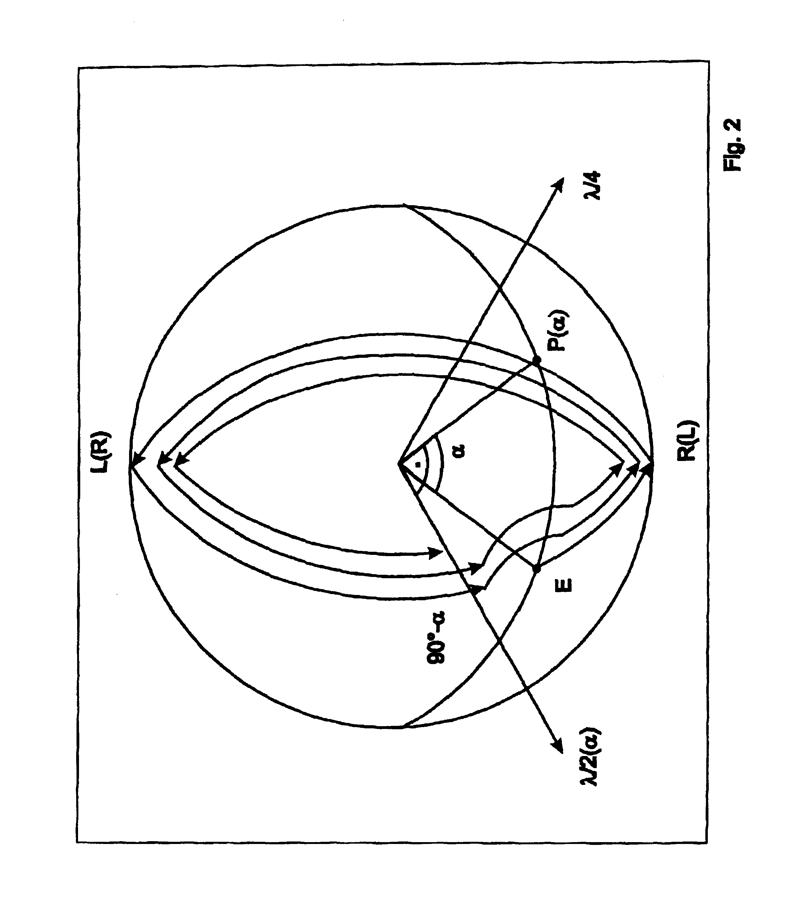
[0025]A phase modulator according to the present invention has at least one electro-optical delay element having a rotatable indicatrix. In this context, the light enters into the phase modulator, undergoes a preset phase shift during transmission through the phase modulator, and then emerges again from the same. In dependence upon the predefined phase shift φ, which may amount to between 0 and 360°, in one specific embodiment, an appropriate electric field is applied via a triggering device to the electro-optical delay element having a rotatable indicatrix, for example a dielectric crystal or a liquid-crystal cell. The principle of applying an electric field to the delay element, i.e., the electric triggering device is available to one skilled in the art, and thus, it will not be explained in greater detail in the following. The electric field is applied to the controllable electro-optical delay element in such a way that the indicatrix of the delay element rotates under the influe...


PUM

PropertyMeasurementUnit
angle of rotationaaaaaaaaaa
angleaaaaaaaaaa
phaseaaaaaaaaaa

Abstract

To provide a phase modulator for introducing a topological phase, which is designed to produce any desired phase shift between zero and 360°, the phase modulator has means, at least one double-refractive, electrooptical delay element having a rotatable indicatrix, which is / are used to direct the polarization of the light, during transmission through the modulator, over at the light one closed path on the Poincaré sphere, the indicatrix rotating in accordance with the predefined phase shift, and the total encircled surface on Poincaré sphere being equal in terms of absolute value to φ.

Description

FIELD OF THE INVENTION[0001]The present invention is directed to a phase modulator and to a method for operating such a phase modulator.BACKGROUND INFORMATION[0002]Diffractive and refractive optical elements operate on the principle of the spatially dependent phase modulation of light. To ensure the modulation to fractions of the wavelength of the light, glass surfaces of the optical components used, for example, should have a high surface accuracy, which entails high manufacturing costs. Of considerable interest are, therefore, inexpensive phase modulators which correct the faulty phase fronts produced by simple optical components, by using a locally varying phase delay. Phase modulators of this kind, however, can, themselves, also be constructed as optical components, for example as lenses or mirrors. In this context, a spatially-dependent voltage is applied-at the phase modulator to change the focal distance of the lens or of the mirror. Another field of application of adaptive o...

Claims


Application Information

Patent Timeline
Patent Type & Authority Patents(United States)
IPC IPC(8): G02F1/01
CPCG02F1/0136
Inventor DULTZ, WOLFGANGSCHMITZER, HEIDRUNBERESNEV, LEONIDDULTZ, GISELA
Owner DEUTSCHE TELEKOM AG
Learn More