
Apparatus and methods for determining critical area of semiconductor design data

Inactive Publication Date: 2005-09-20
KLA TENCOR TECH CORP
View PDF35 Cites 118 Cited by
  • Summary
  • Abstract
  • Description
  • Claims
  • Application Information

AI Technical Summary

Benefits of technology

[0022]These and other features and advantages of the present invention will be presented in more detail in the following ...

Problems solved by technology

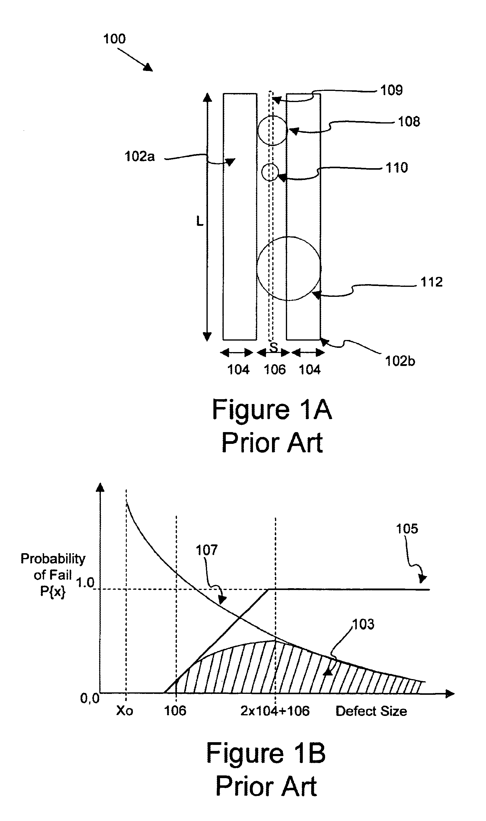
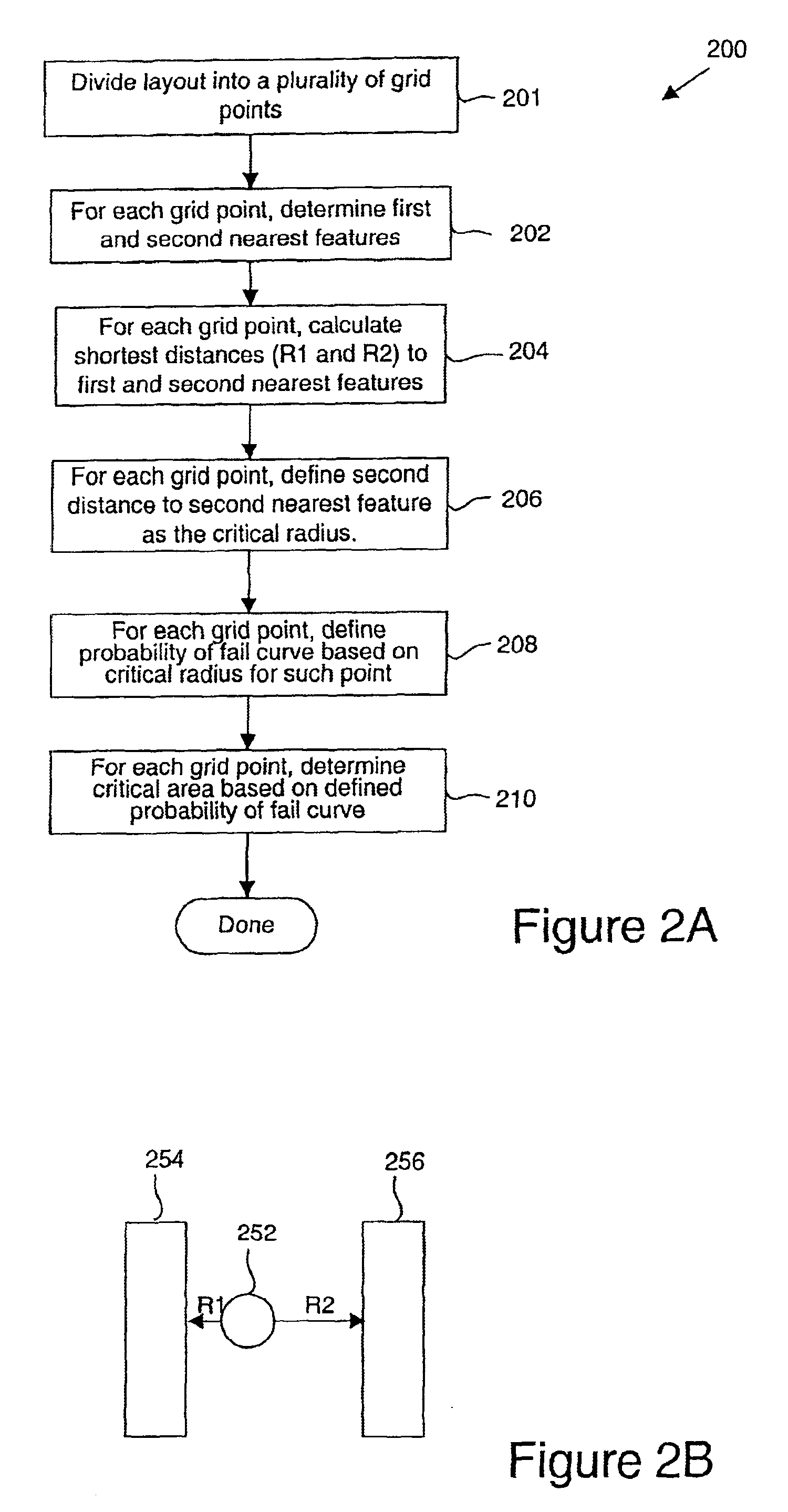
A defect of such radius that falls at this point will touch both the first and second nearest neighboring shapes and cause a fault (a short in this case).

Method used


Image

  • Apparatus and methods for determining critical area of semiconductor design data
  • Apparatus and methods for determining critical area of semiconductor design data
  • Apparatus and methods for determining critical area of semiconductor design data

Examples


Embodiment Construction

[0038]Reference will now be made in detail to a specific embodiment of the invention. An example of this embodiment is illustrated in the accompanying drawings. While the invention will be described in conjunction with this specific embodiment, it will be understood that it is not intended to limit the invention to one embodiment. On the contrary, it is intended to cover alternatives, modifications, and equivalents as may be included within the spirit and scope of the invention as defined by the appended claims. In the following description, numerous specific details are set forth in order to provide a thorough understanding of the present invention. The present invention may be practiced without some or all of these specific details. In other instances, well known process operations have not been described in detail in order not to unnecessarily obscure the present invention.

[0039]The present invention provides efficient mechanisms for calculating the critical area, referred to as ...


PUM


Abstract

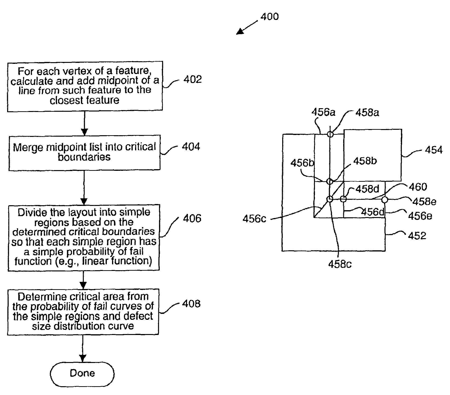
Disclosed are mechanisms for efficiently and accurately calculating critical area. In general terms, a method of determining a critical area for a semiconductor design layout is disclosed. The critical area is utilizable to predict yield of a semiconductor device fabricated from such layout. A semiconductor design layout having a plurality of features is first provided. The features have a plurality of polygon shapes which include nonrectangular polygon shapes. Each feature shape has at least one attribute or artifact, such as a vertex or edge. A probability of fail function is calculated based on at least a distance between two feature shape attributes or artifacts. By way of example implementations, a distance between two neighboring feature edges (or vertices) or a distance between two feature edges (or vertices) of the same feature is first determined and then used to calculate the probability of fail function. In a specific aspect, the distances are first used to determine midlines between neighboring features or midlines within a same feature shape, and the midlines are then used to determine the probability of fail function. A critical area of the design layout is then determined based on the determined probability of fail function. In specific implementations, the defect type is a short type defect or an open type defect. In a preferred implementation, the features may have any suitable polygonal shape, as is typical in a design layout.

Description

CROSS-REFERENCE TO RELATED APPLICATION[0001]This application takes priority under U.S.C. 119(e) of (1) U.S. Provisional Application No. 60 / 338,348 by Akella V. S Satya and Vladmir D. Federov, filed 5 Dec. 2001, entitled “K-T CRITICAL-AREA ALGORITHMS AND SW” and (2) U.S. Provisional Application No. 60 / 346,074 by Akella V. S Satya et al., filed Oct. 25, 2001, entitled “FULL-FLOW INTEGRATED-IC YIELD AND RELIABILITY TEST SITE.” These applications are incorporated herein by reference in their entirety for all purposes.BACKGROUND OF THE INVENTION[0002]This invention relates to methods and apparatus for detecting defect-densities in a semiconductor integrated circuit product and / or test structure to thereby predict product-limited yields and the product lot yields. More particularly, it relates to mechanisms for determining critical area, which is a necessary parameter for, among many purposes including prediction of the end-of-line product yield from the in-line testing and / or inspection ...

Claims


Application Information

Patent Timeline
IPC IPC(8): G06F17/50G01R31/3183
CPCG01R31/318364G06F17/5068H01J2237/2817G06F30/39
Inventor SATYA, AKELLA V. S.FEDEROV, VLADIMIR D.SONG, LI
Owner KLA TENCOR TECH CORP
Learn More