
Food processor with removable blade cartridge

a food processor and cartridge technology, applied in the field of manual type food processors, can solve the problems of difficult to thoroughly clean, inconvenient replacement of blades, etc., and achieve the effects of convenient replacement, convenient food processor cleaning, and convenient removal

Active Publication Date: 2005-09-27
WANGLER ERIC J +1
View PDF18 Cites 27 Cited by
  • Summary
  • Abstract
  • Description
  • Claims
  • Application Information

AI Technical Summary

Benefits of technology

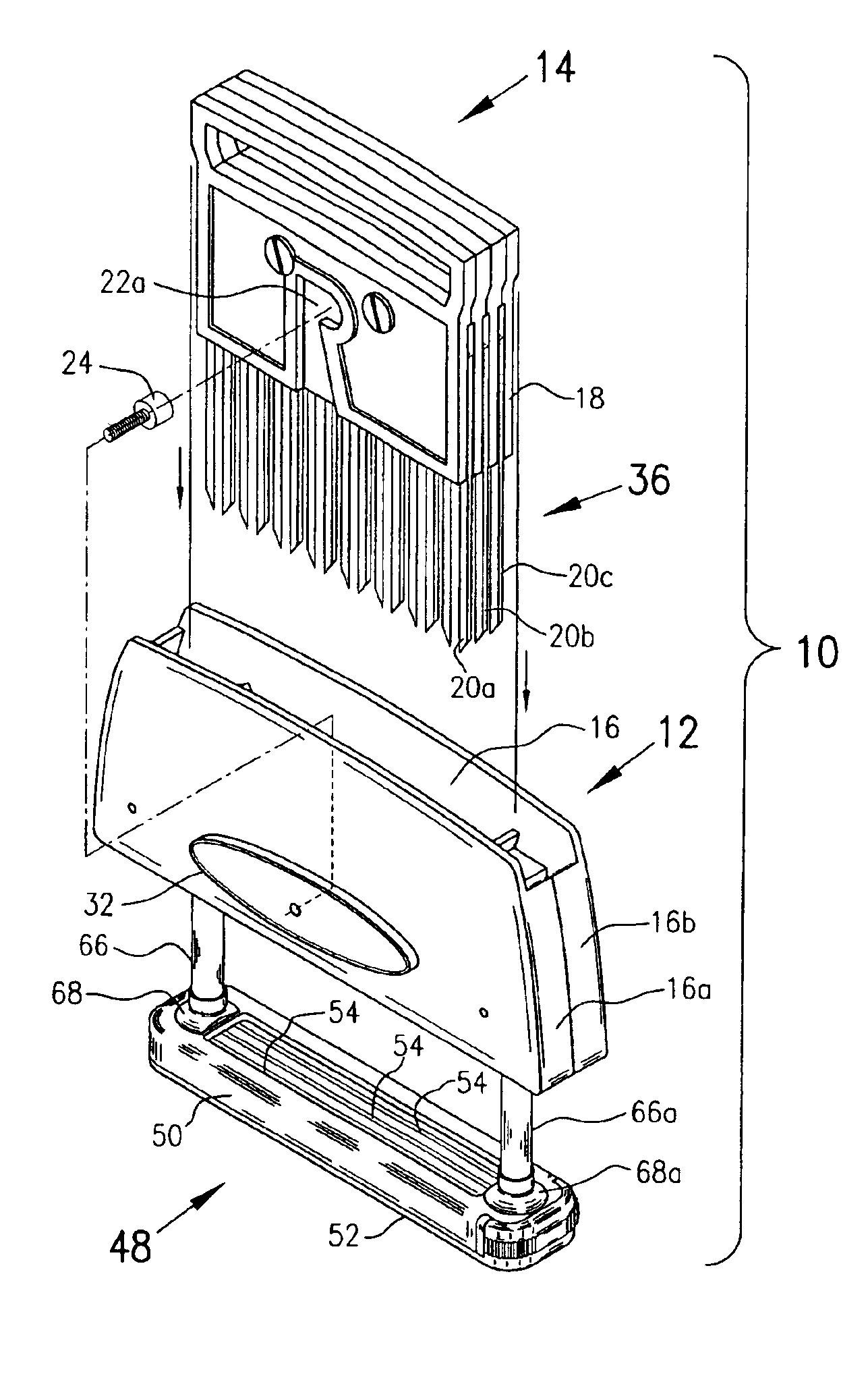
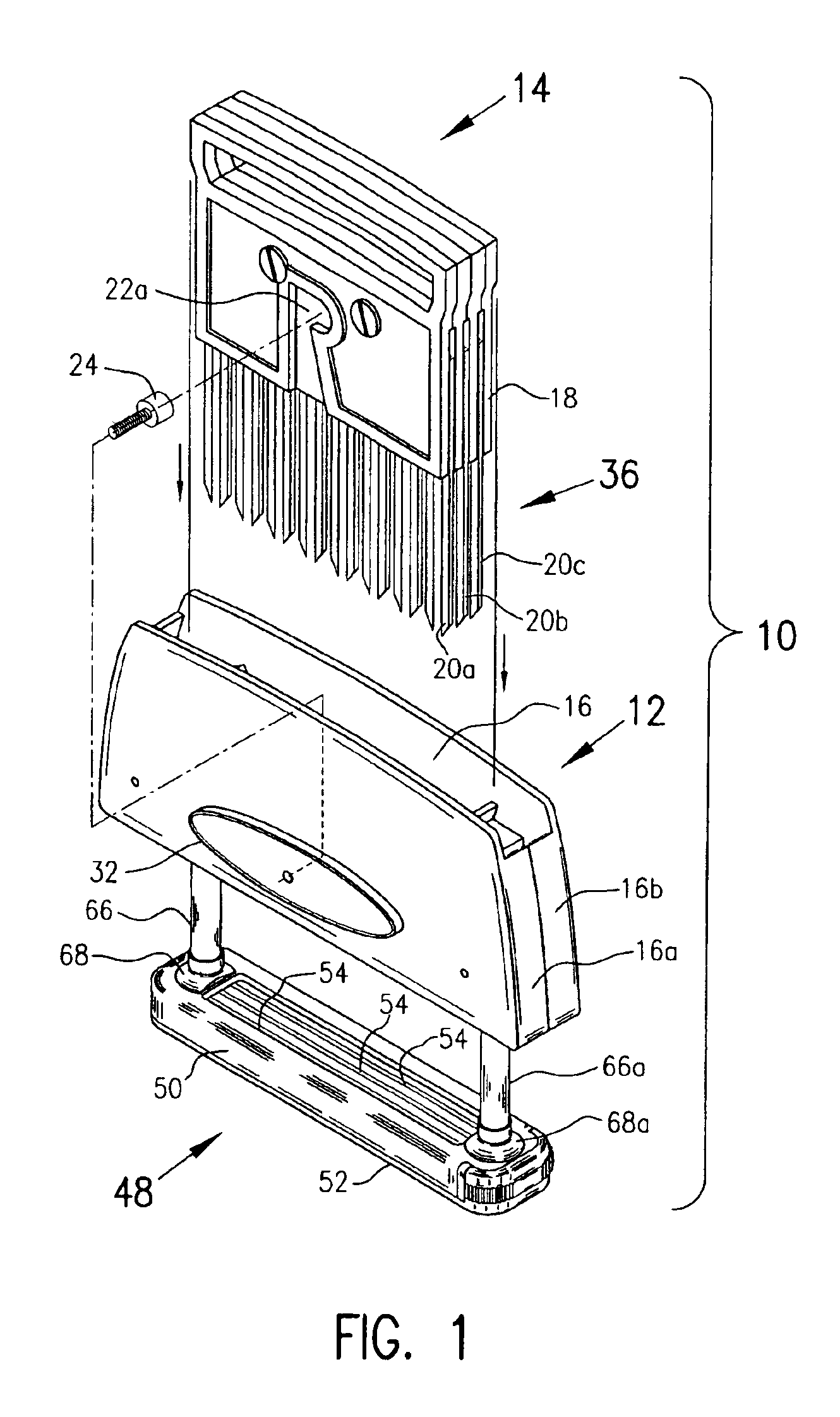
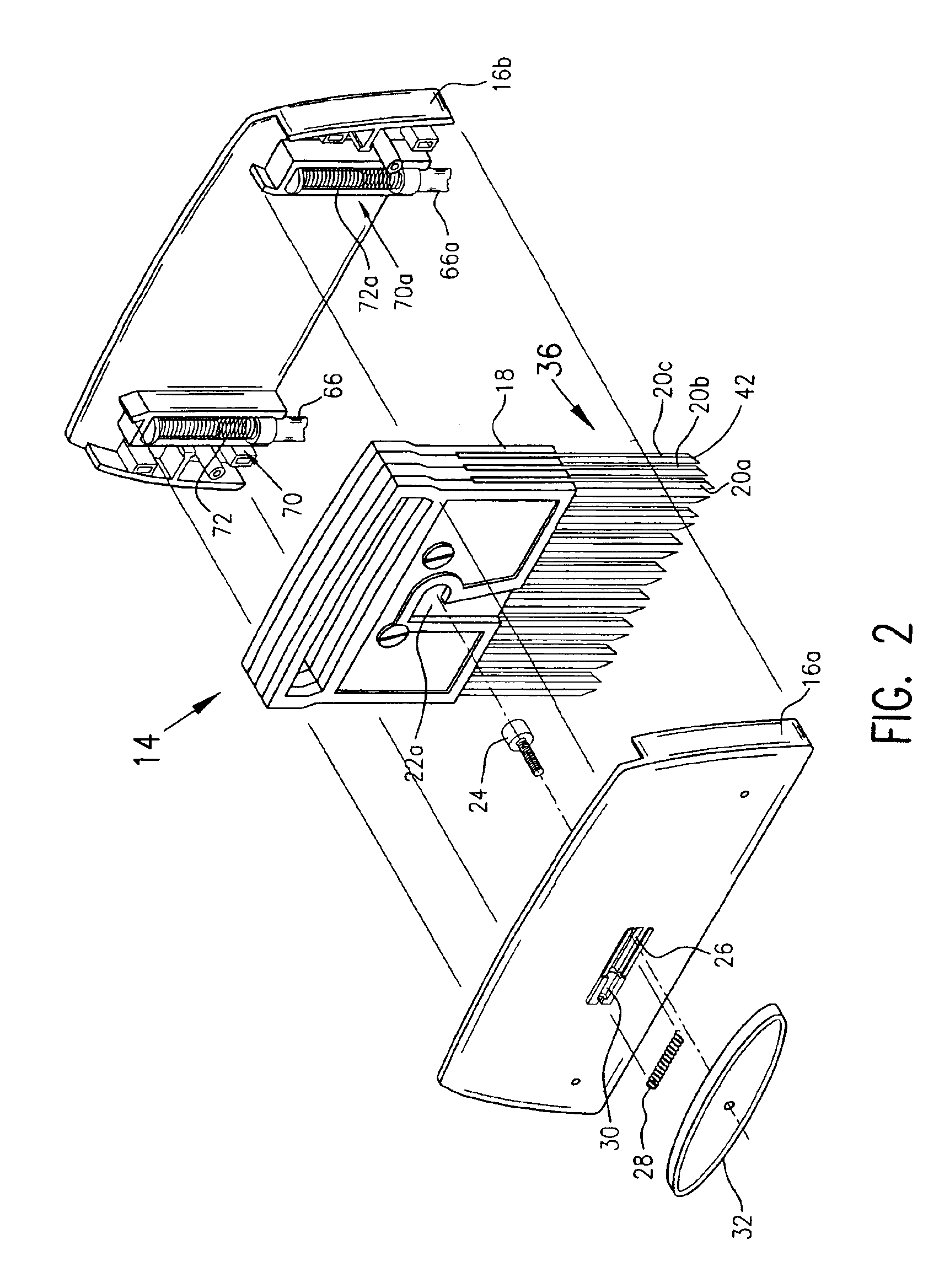
[0009]The invention further includes a food processor having a housing including the above cartridge and a casing holding the cartridge. A quick release lock is provided for locking the cartridge into the casing. In a preferred embodiment, the quick release lock is at least one spring biased latch projection or bolt connected to the casing that protrudes into a recess in the blade holder of the cartridge to securely retain the cartridge in the casing. The cartridge is easily removable from the casing by moving the projection against the spring bias out of the recess to release retention of the cartridge within the casing. It is to be understood that other quick release type locks can be used, e.g. a bolt that is not spring biased into a recess or other bolt retainer but is manually moved into a recess or other bolt retainer and locked there. Such quick release locks for retaining the cartridge in the casing make the cartridge easy to replace and make the food processor easy to clean.
[0010]The invention also includes a food processor having a housing that has at least one blade and preferably at least one series of longitudinally aligned blades for piercing and cutting food where each of the blades has side surface portions and a cutting tip edge portion. A base is provided with openings through which the blades can pass to pierce and cut food. The base includes a fixed base portion and a removable base portion. The removable base portion is provided with a sufficient number of longitudinal slots, open at one end of the slots, so that the slots in the removable base portion can be placed over the side surface portions of the blades without encountering the cutting tip edge portions of the blades. The removable base portion can be easily secured to the fixed base portion and easily removed from the fixed base portion utilizing a quick release latch mechanism for ease in cleaning and replacement.
[0011]The fixed base portion is secured to the housing by a retracting mechanism that permits retraction of the base relative to the housing so that upon retraction, the blades extend through the slots and beyond the base to pierce and cut food in contact with the base. Preferably, the slots in the removable base portion widen proximate the open end of the slots to assist in guiding the blades into the slots and the retracting mechanism securing the housing to the fixed base portion includes a pair of tubes at opposing ends of the fixed base portions that fit into retaining cavities in the housing and housing springs within the housing that outwardly bias the tubes so that points of the blades are within the slots and do not extend beyond the base and so that a force applied to drive the housing toward the base causes compression of the housing springs permitting the tubes to further enter the housing thus reducing distance between the housing and the base thus causing the blades to extend through the slots and beyond the base to pierce and cut food in contact with the base.

Problems solved by technology

Such tenderizer apparatuses have a significant disadvantage in that it is very difficult to thoroughly clean them and it is very difficult to replace the blades.
Certainly replacement of the blades is sufficiently inconvenient that blades of different configurations for different functions could not routinely be changed during use of the apparatus.
This is further aggravated by the fact that points on blades 35 readily catch on the sides of slots 57 thus making reassembly by inserting pointed ends of the blades into the slots impracticably difficult.
Disassembly for cleaning and reassembly after cleaning is similarly difficult.
As a further disadvantage, the complex assembly structure of the apparatus described in U.S. Pat. No. 4,199,841, make initial assembly for new products difficult thus adding significant cost to the product.
Replacement of blades may be accomplished by inverting the steps as described above with respect to disassembly; however, reversal of the steps is more difficult.
In particular, it is very difficult to retain all parts in their proper positions while the case halves 22a and 22b are reassembled.
Tapering of the slits near their tops in fact does not help as the points of the blades are even more likely to become stuck on the more horizontally oriented tapered surfaces.
The use of the cartridge having plate holder 14 causes a further problem in that it is not even possible to insert the blades from an end opposite the blade points, i.e. the plate holder 14 cannot be inserted through the slits 35 that are narrower than the plate holder.

Method used


Image

  • Food processor with removable blade cartridge
  • Food processor with removable blade cartridge
  • Food processor with removable blade cartridge

Examples


Embodiment Construction

[0020]An important aspect of one embodiment of the present invention is that a cartridge, containing a series of knife blades, is provided for a hand operated food processor that is easily removed from and replaced into a food processor thus permitting easy cleaning and blade replacement. The food processor is most commonly a meat tenderizer that causes a series of blades to enter into meat and cut meat fibers when downward pressure is applied to the food processor as its base or foot sits on meat to be processed. The cartridge includes a blade holder having at least one demi-lock for cooperating with a demi-lock on a casing for the cartridge to form a quick release lock that holds the cartridge in the casing. In a preferred embodiment, the quick release lock includes a recess in a blade holder of the cartridge for receiving a spring biased latch projection from the casing for retaining the cartridge in the casing.

[0021]In addition to the blade holder, the cartridge includes at leas...


PUM


Abstract

A cartridge for a hand operated food processor including a blade holder holding at least one blade. A quick release lock is provided for retaining the cartridge in a casing. The cartridge preferably includes at least one series of aligned blades held by the blade holder utilizable for piercing and cutting food. The invention further includes a food processor having a housing including the above cartridge and a casing holding the cartridge. The invention also includes a food processor having a housing that has at least one blade and preferably at least one longitudinal series of blades for piercing and cutting food where each of the blades has side surface portions and a cutting tip edge portion. A base is provided with openings through which the blades can pass to pierce and cut food. The base includes a fixed base portion and a removable base portion. The removable base portion is provided with a sufficient number of longitudinal slots, open at one end of the slots, so that the slots in the removable base portion can be placed over the side surface portions of the blades without encountering the cutting tip edge portions of the blades. The removable base portion can be easily secured to the fixed base portion and easily removed from the fixed base portion utilizing a quick release latch mechanism. The fixed base portion is secured to the housing by a retracting mechanism that permits retraction of the base relative to the housing so that upon retraction the blades extend through the slots to process food in contact with the bottom of the base.

Description

BACKGROUND OF THE INVENTION[0001]This invention relates to food processors and more particularly relates to manual type food processors where blades are downwardly forced onto food product to cut it, chop it or tenderize it. The invention especially relates to mechanical meat tenderizers where a plurality of knives are inserted into meat product to cut tough fibrous material to make the meat easier to chew.[0002]Numerous food processors are known where blades are manually forced downwardly onto food product to cut, chop or tenderize it. For example, meat tenderizer apparatuses are known that have a plurality of knives that are forced into the meat as described in U.S. Pat. No. 4,199,841 and U.S. Pat. No. 4,870,717. Such tenderizer apparatuses have a significant disadvantage in that it is very difficult to thoroughly clean them and it is very difficult to replace the blades. Certainly replacement of the blades is sufficiently inconvenient that blades of different configurations for d...

Claims


Application Information

Patent Timeline
IPC IPC(8): A22C9/00
CPCA22C9/008
Inventor KUJAWSKI, STANLEY M.WANGLER, ERIC J.CALDWELL, BRADLEY
Owner WANGLER ERIC J
Learn More