Keyboard illumination for computing devices having backlit displays

a technology of computing devices and backlit displays, which is applied in computing, details of portable computers, instruments, etc., can solve the problems of reduced usage time of portable computers between recharges from external power sources, inability to see the keyboard and the individual keys of the keyboard in such conditions, and additional power for the ligh

Inactive Publication Date: 2005-09-27
IBM CORP
View PDF6 Cites 250 Cited by
  • Summary
  • Abstract
  • Description
  • Claims
  • Application Information

AI Technical Summary

Problems solved by technology

However, the keyboard and the individual keys making up the keyboard may not be able to be seen in such conditions.
The provision of a separate light suffers from the disadvantage that additional power is needed for the light and so the usage time of the portable computer between recharges from the external power source is reduced.
Since a portable computer is typically closed when not in use, the recharging cannot be readily achieved by normal ambient light.
The light from the backlight is coupled through a light pipe coupler, which may restrict the angle of use of the display panel with respect to the keyboard.

Method used


Image

  • Keyboard illumination for computing devices having backlit displays
  • Keyboard illumination for computing devices having backlit displays
  • Keyboard illumination for computing devices having backlit displays

Examples


first embodiment

[0028]FIG. 5 shows an adjustment mechanism to adjust the amount of light which reaches the keyboard. This mechanism operates by aligning, misaligning or partially aligning the fiber-optic cables so as to implement an intensity control. Portions 502 and 504 are made of material which is substantially optically transparent. Light enters the adjustment mechanism at face 510. Light leaves the adjustment mechanism at face 512. Portion 504 is arranged to slide along portion 502 in the direction shown by arrow 506. Typically, the movement of portion 504 may be achieved by means of a user control. A resilient means may apply pressure to either or both of surfaces 510, 512, so as to encourage portions 504 and 502 in a direction opposite to that of arrow 506. A user control force may then be applied in direction 506.

second embodiment

[0029]FIG. 6 shows the invention in which two optical fibers 602, 604 are merely positioned so that in one position they are aligned and in other positions along the axis of arrow 606 they are partially or entirely misaligned.

[0030]It is well known that certain colors of light are more suitable if it is desired to retain “night vision”, that is the ability to see dim points of light in the distance outside. Looking at brightly lit objects or at objects lit with white light can cause the eye to adjust for the brightly lit object and take some time to re-adjust so as to be able to see the less bright objects outside. Typically a red color is used, for example, on board ships. Similarly, it may be desired that a certain color of light is used for maximum legibility. In photographic darkrooms, it may be desirable to use a particular color of light in order to avoid exposure of undeveloped photographic films.

[0031]FIG. 7 shows a mechanism for controlling the color of light which is used ...


PUM


Abstract

Apparatus is disclosed for illumination of a keyboard in a computing device having a display contained in a portion of the computing device which is hingeably attached to a keyboard portion, the display having a backlight. The system comprises one or more translucent elements associated with the keyboard and one or more light-conducting fibers for conducting light from the backlight of the backlit display to the one or more translucent elements associated with the keyboard. The level of illumination is varied by means of the one or more light conducting fibers transmitting light through two portions of transparent material, the two portions of transparent material have an area of contact between them which may be varied. A color adjustment mechanism is also provided.

Description

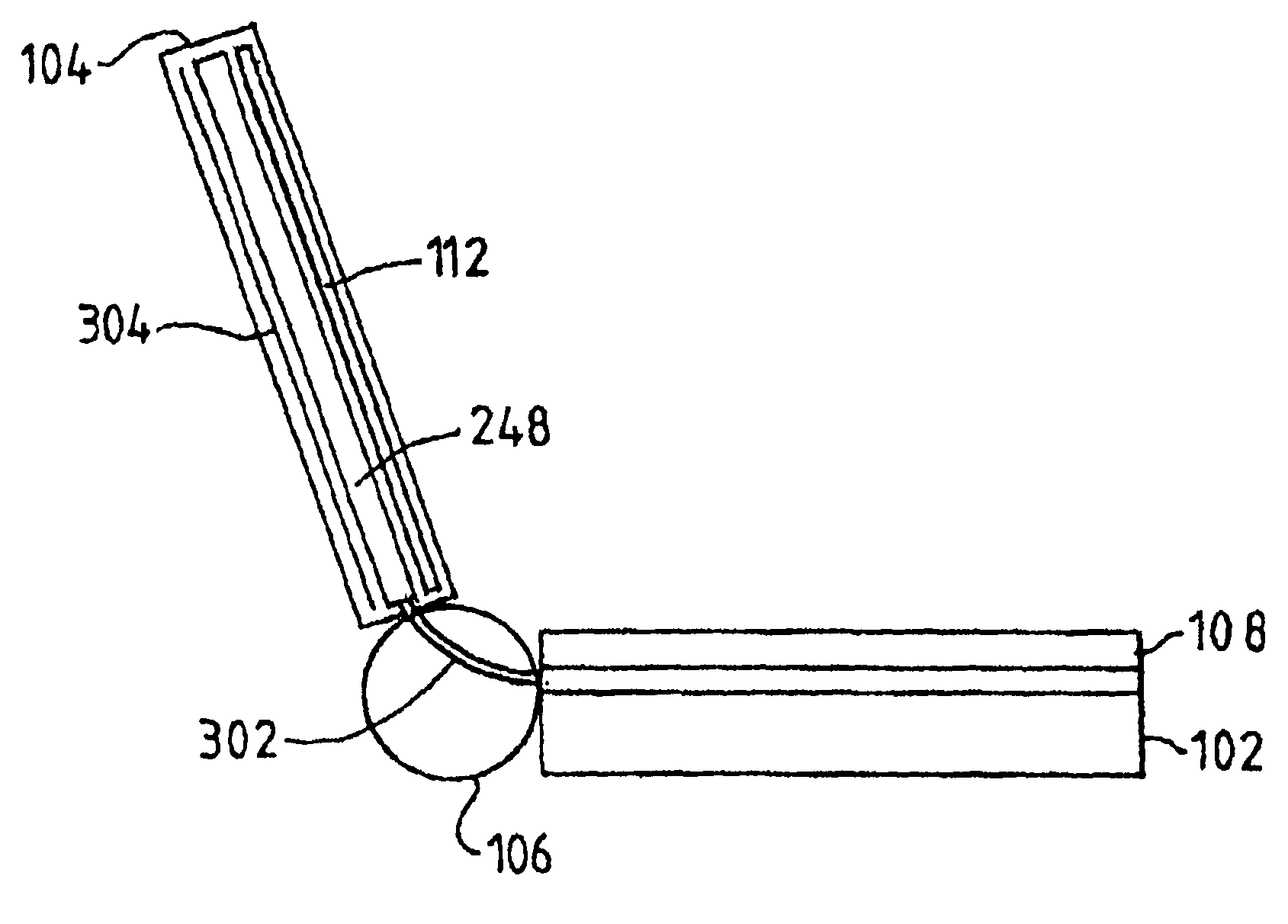
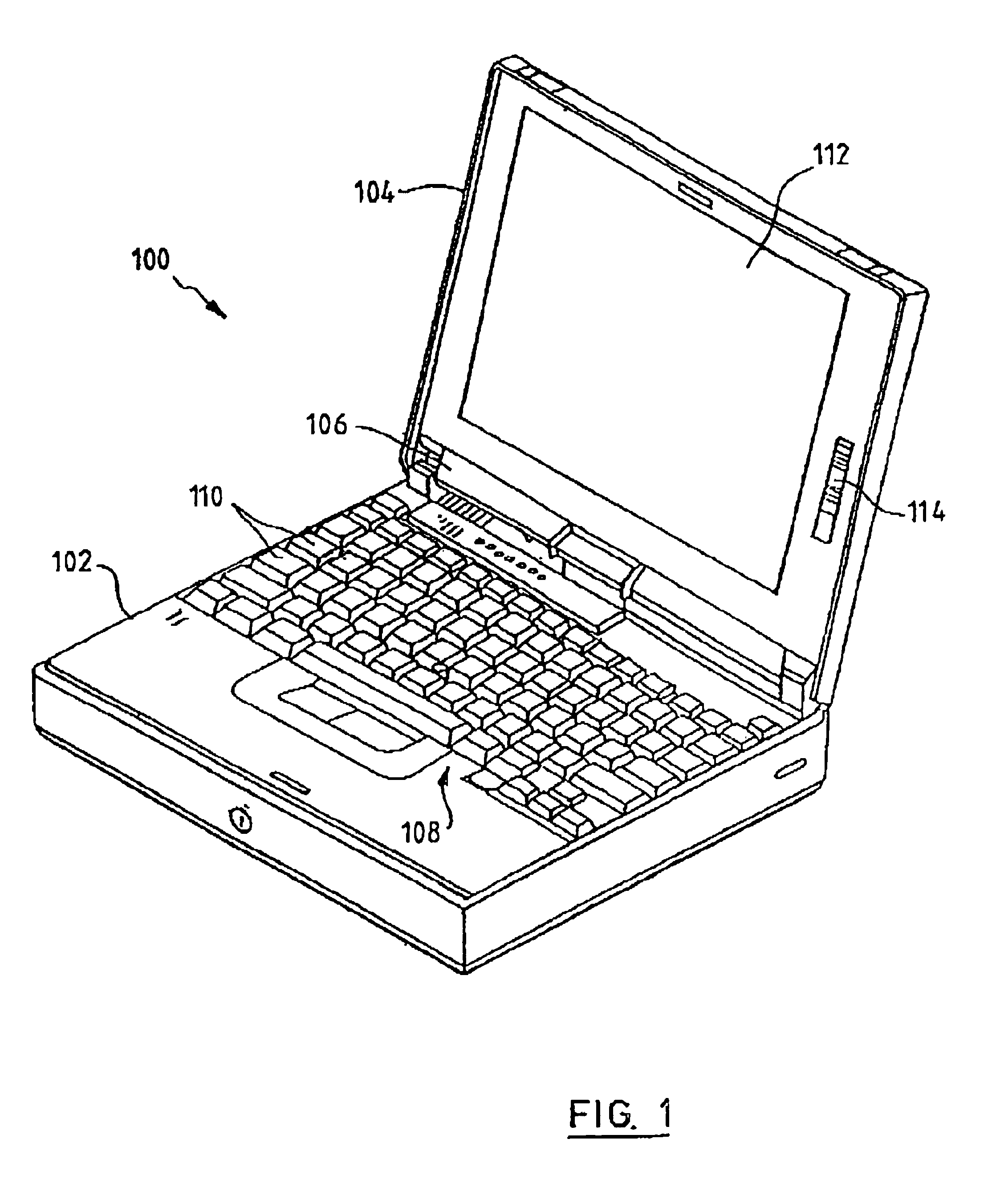
FIELD OF THE INVENTION[0001]The present invention relates to computing devices having an integral light source for a display panel and to the use of light from that integral light source for illumination of the keyboard of the computing device. More particularly, the present invention relates to the provision of a light path between the light source and the keyboard and to an intensity control and a color control for such illumination.BACKGROUND OF THE INVENTION[0002]A conventional portable computer can be used in many places with its in-built power source without the need for attachment to an external power source. In some of the places where a portable computer can be used, there is a low ambient light level. Examples of such environments having low ambient light levels include conference rooms during presentations, on aircraft or in cars. In areas where there is a low ambient light level, the display may be clearly seen as the display on a portable computer is typically backlit. ...

Claims


Application Information

Patent Timeline
Patent Type & Authority Patents(United States)
IPC IPC(8): G06F1/16
CPCG06F1/1616G06F1/1662G06F3/0202
Inventor KNOX, ANDREW RAMSEYLONGOBARDI, GIUSEPPE
Owner IBM CORP
Why Eureka
Try Eureka