Dynamically alterable three-dimensional graphical model of a body region

a three-dimensional graphical model and dynamically adjustable technology, applied in the field of dynamically adjustable three-dimensional graphical models of body regions, can solve the problems of difficult to navigate the catheter to the appropriate location, difficult for the physician to be certain of the catheter position, and inability to endoscopic visualization of the treatment site within the body, etc., to achieve the effect of increasing the conformity

Inactive Publication Date: 2005-09-27
BOSTON SCI SCIMED INC
View PDF76 Cites 412 Cited by
  • Summary
  • Abstract
  • Description
  • Claims
  • Application Information

AI Technical Summary

Benefits of technology

[0010]The present invention is a system and method for graphically displaying a three-dimensional model of a region located within a living body. A three-dimensional model of a region of interest is generated for display on a graphical display. The location in three-dimensional space of a physical characteristic (e.g. a structure, wall or space) in the region of interest is determined using at least one probe positioned within the living body. The model is deformed to approximately reflect the determined three-dimensional location of the physical characteristic and the model as deformed is displayed. Preferably, the probe or probes are moved throughout the region of interest so as to gather multiple data points that can be used to increase the conformity between the model and the actual region of interest within the patient.

Problems solved by technology

For certain types of minimally invasive medical procedures, endoscopic visualization of the treatment site within the body is unavailable or does not assist the clinician in guiding the needed medical devices to the treatment site.
Because the fluoroscopic image is in two-dimensions and has fairly poor resolution, it may be difficult for the physician to be certain of the catheter positions.
Thus, for example, once a physician has identified an area which is to be ablated (using a map of the measured electrical activity of the heart) it may be difficult to navigate an ablation catheter to the appropriate location in order to accurately ablate the area of concern.

Method used


Image

  • Dynamically alterable three-dimensional graphical model of a body region
  • Dynamically alterable three-dimensional graphical model of a body region
  • Dynamically alterable three-dimensional graphical model of a body region

Examples


Embodiment Construction

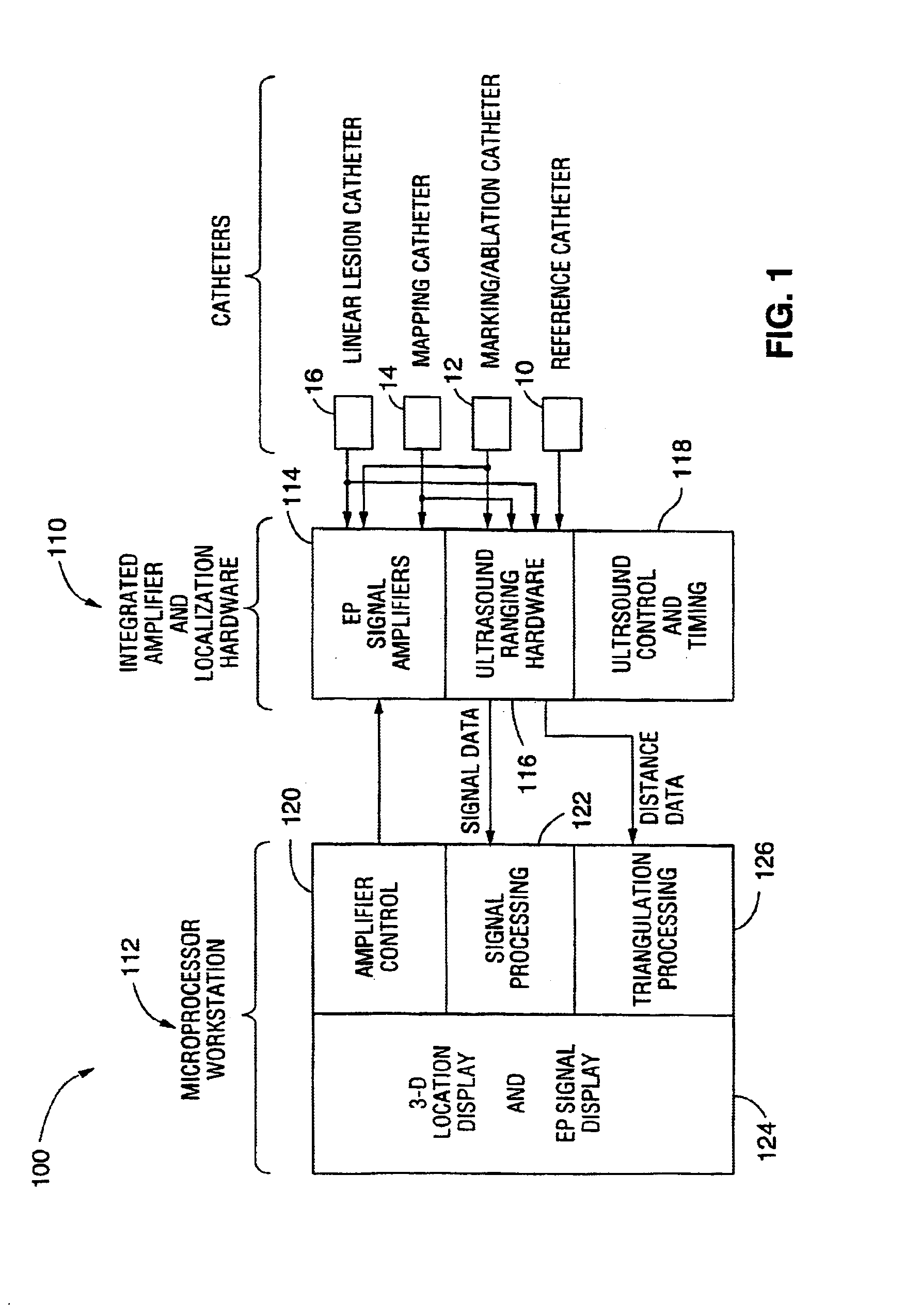
[0065]The model transformation system and method is designed for use in combination with a localization system that permits determination of the 3-D position of a medical device within a body. From the determined 3-D position, the 3-D locations of anatomical features in a region of interest may be derived and used to deform a 3-D graphical model of the region of interest so as to dynamically increase the conformity of the model with the actual region of interest.

[0066]Various types of prior art localization systems may be used in combination with the deformable model according to the present invention. Once such localization system is described U.S. Pat. Nos. 5,391,199, 5,443,489, 5,480,422, 5,546,951, 5,568,809, 5,694,945 and 5,713,946 (each to Ben-Haim) which are incorporated herein by reference. That system utilizes antennas placed outside the body and on catheters placed within the heart. Electromagnetic fields are passed between the antennas and used to determine the locations ...


PUM


Abstract

The present invention is a system and method for graphically displaying a three-dimensional model of a region located within a living body. A three-dimensional model of a region of interest is displayed on a graphical display. The location in three-dimensional space of a physical characteristic (e.g. a structure, wall or space) in the region of interest is determined using at least one probe positioned within the living body. The graphical display of the model is deformed to approximately reflect the determined three-dimensional location of the physical characteristic. Preferably, the probe or probes are moved throughout the region of interest so as to gather multiple data points that can be used to increase the conformity between the graphical display and the actual region of interest within the patient.

Description

FIELD OF THE INVENTION[0001]The present invention relates to a system for creating a three-dimensional graphical model of a region within a living body and for dynamically altering the graphical model to increase its conformity with the actual region in the patient's body using physical characteristics acquired from a medical device probing the region of interest.BACKGROUND OF THE INVENTION[0002]For certain types of minimally invasive medical procedures, endoscopic visualization of the treatment site within the body is unavailable or does not assist the clinician in guiding the needed medical devices to the treatment site.[0003]Examples of such procedures are those used to diagnose and treat supra-ventricular tachycardia (SVT), atrial fibrillation (AF), atrial flutter (AFL) and ventricular tachycardia (VT). SVT, AFL, AF and VT are conditions in the heart which cause abnormal electrical signals to be generated in the endocardial tissue to cause irregular beating of the heart.[0004]A ...

Claims


Application Information

Patent Timeline
Patent Type & Authority Patents(United States)
IPC IPC(8): A61B19/00A61B5/042A61B5/107A61B8/00A61B8/12A61B17/00A61B18/12
CPCA61B6/541A61B8/12A61B8/4245A61B8/445A61B2017/00053A61B2017/00243A61B34/10A61B5/287Y10S128/92Y10S128/922
Inventor WILLIS, N. PARKERZENG, JINGLINQUARATO, JAMES A.
Owner BOSTON SCI SCIMED INC
Why Eureka
Try Eureka