Method and circuit for detecting cardiac rhythm abnormalities by analyzing time differences between unipolar signals from a lead with a multi-electrode tip

a multi-electrode tip and time difference technology, applied in the field of cardiac leads, can solve the problems of affecting the patient's health, affecting the patient's comfort,

Inactive Publication Date: 2005-09-27
ST JUDE MEDICAL
View PDF19 Cites 75 Cited by
  • Summary
  • Abstract
  • Description
  • Claims
  • Application Information

AI Technical Summary

Benefits of technology

[0011]It is an object of the present invention to provide a method and a circuit for analyzing signals obtained with a ca...

Problems solved by technology

Moreover, at least in the case of a defibrillator, unnecessary triggering of the extremely strong defibrillation energy will cause considerable discomfort to the pa...

Method used


Image

  • Method and circuit for detecting cardiac rhythm abnormalities by analyzing time differences between unipolar signals from a lead with a multi-electrode tip
  • Method and circuit for detecting cardiac rhythm abnormalities by analyzing time differences between unipolar signals from a lead with a multi-electrode tip
  • Method and circuit for detecting cardiac rhythm abnormalities by analyzing time differences between unipolar signals from a lead with a multi-electrode tip

Examples


Embodiment Construction

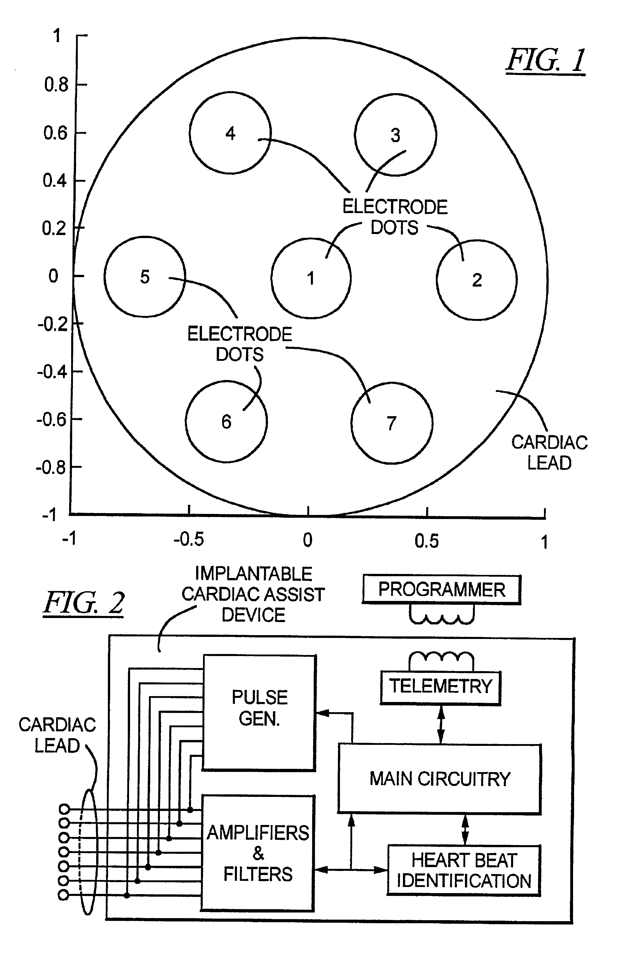
[0031]An embodiment of an electrode lead for use with the circuit and method in accordance with the principles of the present invention is shown in FIG. 1, which is a view looking directly at the distal tip (greatly enlarged) of the cardiac lead. As can be seen in FIG. 1, the lead tip has a number of electrode dots distributed thereon, including a centrally disposed electrode dot 1 and a number of other electrode dots arranged relative to the centrally disposed electrode dot 1. In the embodiment of FIG. 1, six other electrode dots 2-7 are shown, for a total of seven electrode dots in the embodiment of FIG. 1. In the embodiment of FIG. 1, the electrode dots 2-7 are shown as being annularly arranged around the centrally disposed electrode dot 1, however, other locations are possible.

[0032]The axes shown in FIG. 1 are in arbitrary units and are solely for the purpose of providing a guide as to the relative placement of the electrode dots 1-7. Each electrode dot will have a diameter of ...


PUM


Abstract

A circuit and method for detecting cardiac rhythm abnormalities employ unipolar signals respectively obtained from a cardiac lead having a tip at which a number of separate electrodes are disposed, the electrodes being simultaneously in contact with cardiac tissue. The respective unipolar signals which are obtained from the multiple electrodes exhibit a time relationship relative to each other, and this time relationship is analyzed to determine whether a cardiac rhythm abnormality is present or one or more of the unipolar signals is compared to a template which is known to represent a cardiac abnormality. Analysis of the time relation is undertaken by determining the absolute value of a time offset between any two of the unipolar signals, or by correlating any two of the unipolar signals.

Description

BACKGROUND OF THE INVENTION[0001]1. Field of the Invention[0002]The present invention is directed to a cardiac lead suitable for use in pacemakers, cardioverters, defibrillators, and the like, as well as to a method and circuit for using such a lead to detect cardiac rhythm abnormalities, such as fibrillation and tachycardia.[0003]2. Description of the Prior Art[0004]A cardiac lead typically has a proximal end with a connector adapted for electrical and mechanical connection to a cardiac-assist device, such as a pacemaker, cardioverter or defibrillator, and an opposite distal end, at which one or more electrodes is / are located. Between the distal end and the proximal end, the lead has a flexible insulating sheath or jacket, containing one or more conductors, depending on the number of electrodes.[0005]The electrodes are exposed conductive surfaces at the distal end of the lead. Conventional electrode configurations include a unipolar configuration and a bipolar configuration. In a u...

Claims


Application Information

Patent Timeline
IPC IPC(8): A61N1/362A61N1/39
CPCA61N1/3622A61N1/3956Y10S128/923
Inventor BJÖRLING, ANDERSHEDBERG, SVEN-ERIKLINDEGREN, ULFLINDGREN, ANDERS
Owner ST JUDE MEDICAL
Why Eureka
Try Eureka