Gas turbine engine combustor can with trapped vortex cavity

a technology of combustor cans and gas turbine engines, which is applied in the direction of machines/engines, mechanical equipment, lighting and heating apparatus, etc., can solve the problems of mandated limits, and inability to meet the requirements of combustion

Inactive Publication Date: 2005-10-04
GENERAL ELECTRIC CO
View PDF29 Cites 64 Cited by
  • Summary
  • Abstract
  • Description
  • Claims
  • Application Information

AI Technical Summary

Problems solved by technology

Electrical power generating gas turbine engines are typically operated for extended periods of time and exhaust emissions from the combustion gases are a concern and are subject to mandated limits.
Lean burning pre-mixed low NOx combustors have been designed to produce low exhaust emissions but are susceptible to combustion instabilities in the combustion chamber.
Diatomic nitrogen rapidly disassociates at temperatures exceeding about 3000.degree. F. and combines with oxygen to produce unacceptably high levels of NOx emissions.
However, water / steam injection is a relatively expensive technique and can cause the undesirable side effect of quenching carbon monoxide (CO) burnout reactions.
Additionally, water / steam injection methods are limited in their ability to reach the extremely low levels of pollutants required in many localities.
Lean pre-mixed low NOx combustors are more susceptible to combustion instability in the combustion chamber which causes the fuel and air mixture to vary, thus, lowering the effectiveness of the combustor to reduce emissions.
Lean burning low NOx emission combustors with pre-mixers are subject to combustion instability that imposes serious limitations upon the operability of pre-mixed combustion systems.

Method used


Image

  • Gas turbine engine combustor can with trapped vortex cavity
  • Gas turbine engine combustor can with trapped vortex cavity
  • Gas turbine engine combustor can with trapped vortex cavity

Examples


Embodiment Construction

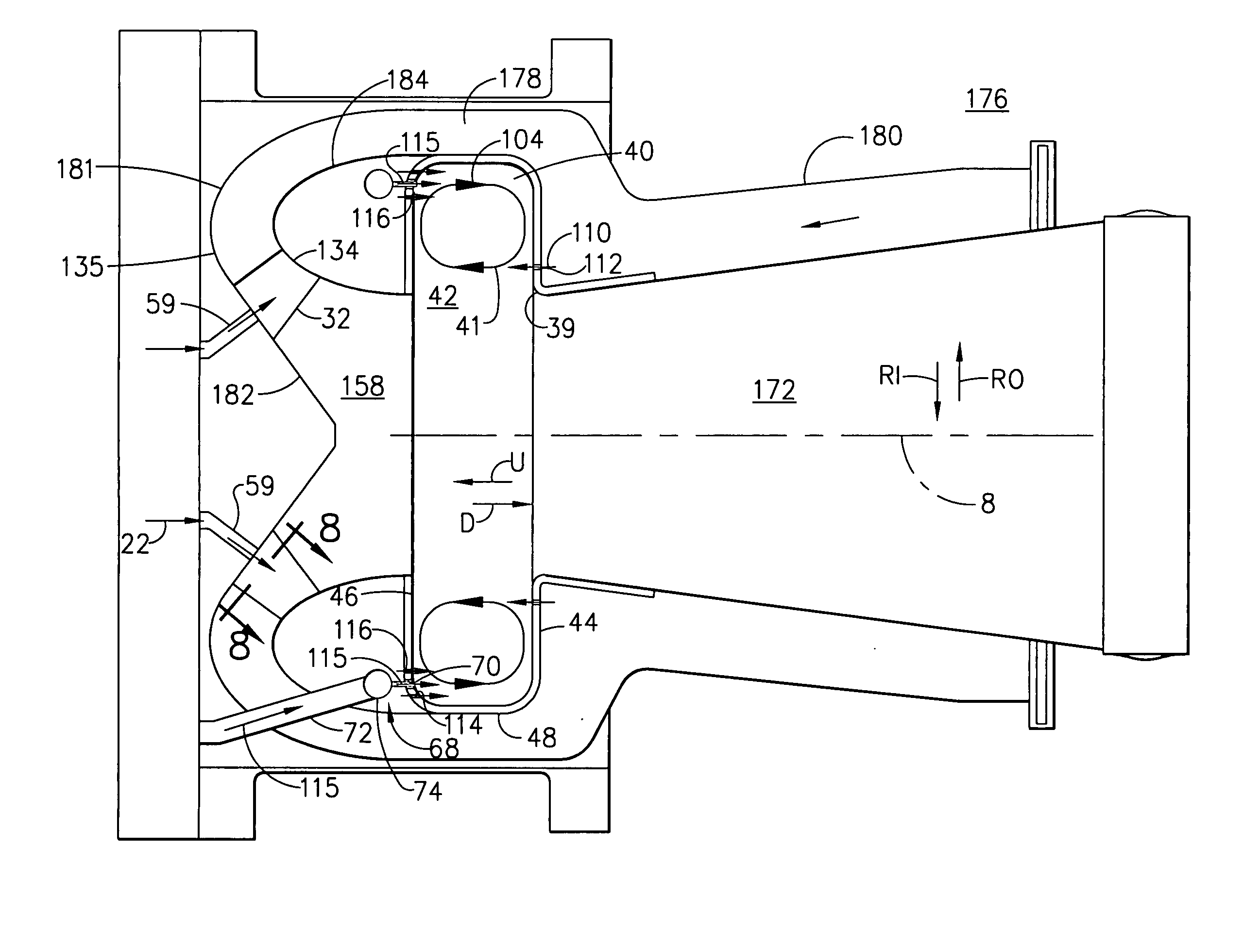
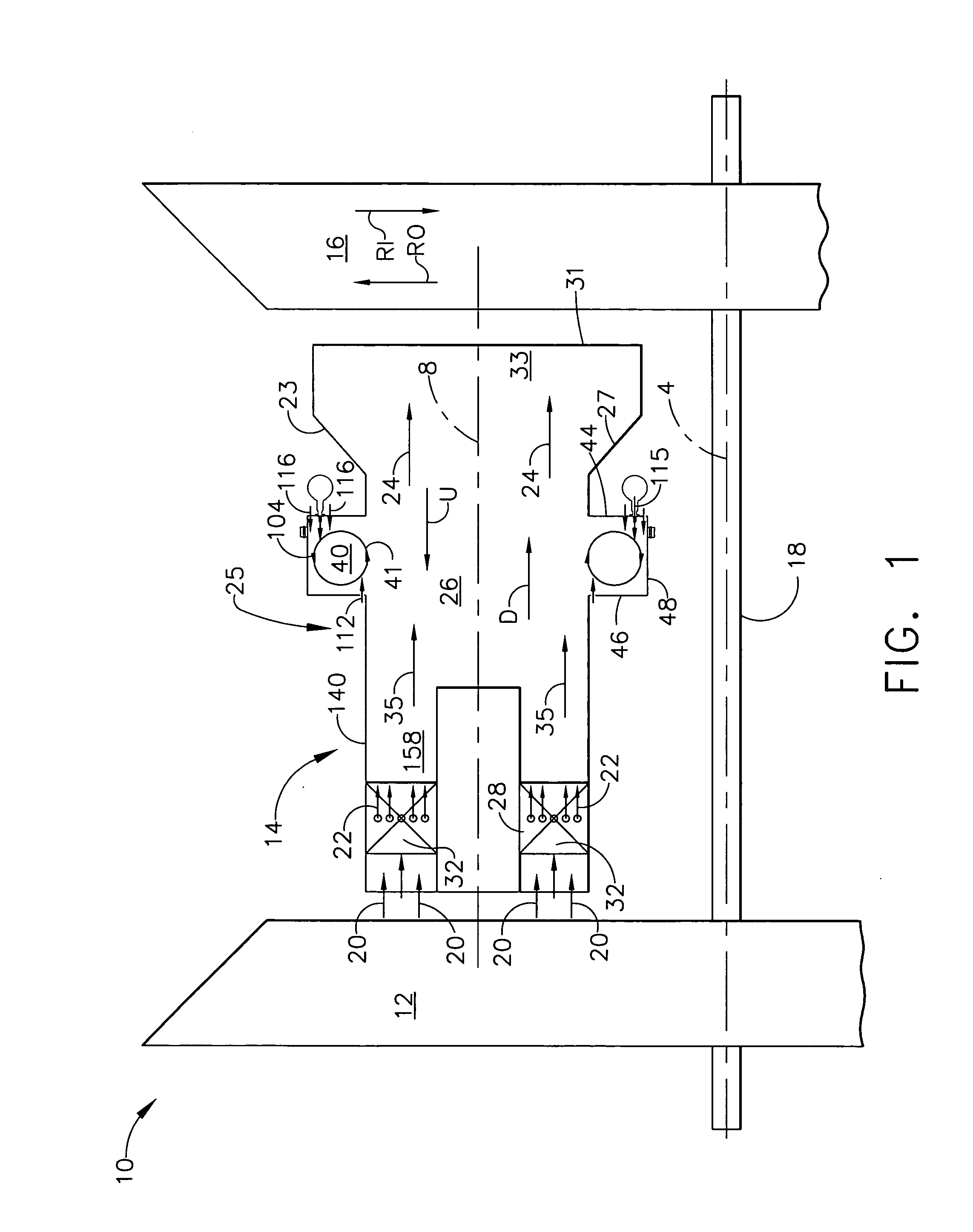
[0024]Illustrated in FIG. 1 is an exemplary industrial gas turbine engine 10 including a multi-stage axial compressor 12 disposed in serial flow communication with a low NOx combustor 14 and a single or multi-stage turbine 16. The turbine 16 is drivingly connected to compressor 12 by a drive shaft 18 which is also used to drive an electrical generator (not shown) for generating electrical power. During operation, the compressor 12 discharges compressed air 20 in a downstream direction D into the combustor 14 wherein the compressed air 20 is mixed with fuel 22 and ignited for generating combustion gases 24 from which energy is extracted by the turbine 16 for rotating the shaft 18 to power compressor 12 and driving the generator or other suitable external load. The combustor 14 is can-annular having a plurality of combustor can assemblies 25 circumferentially disposed about an engine centerline 4.

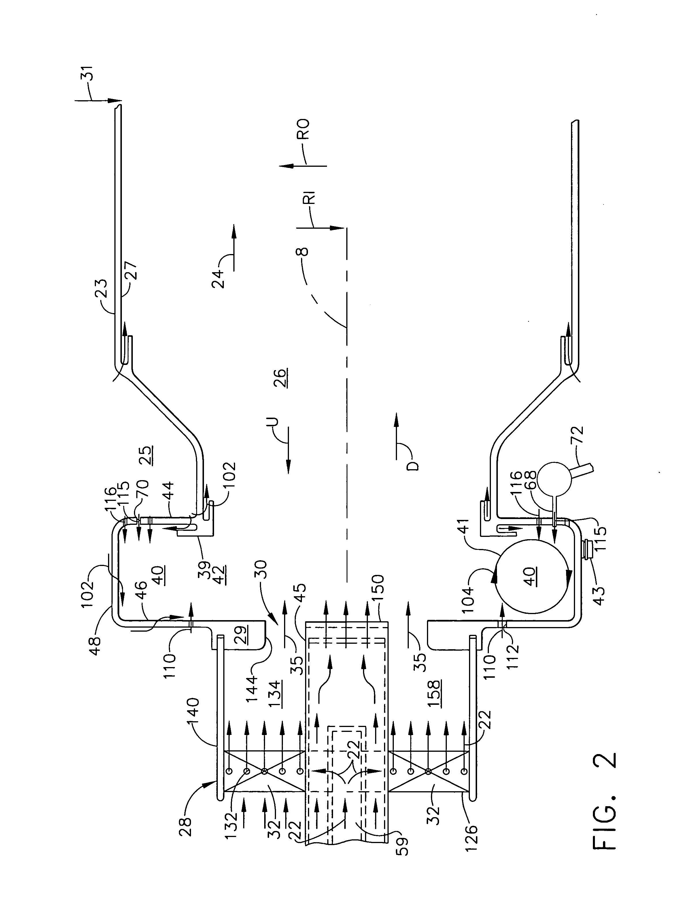
[0025]Referring further to FIG. 2, each of the combustor can assemblies 25 includes a com...


PUM


Abstract

A gas turbine engine combustor can downstream of a pre-mixer has a pre-mixer flowpath therein and circumferentially spaced apart swirling vanes disposed across the pre-mixer flowpath. A primary fuel injector is positioned for injecting fuel into the pre-mixer flowpath. A combustion chamber surrounded by an annular combustor liner disposed in supply flow communication with the pre-mixer. An annular trapped dual vortex cavity located at an upstream end of the combustor liner is defined between an annular aft wall, an annular forward wall, and a circular radially outer wall formed therebetween. A cavity opening at a radially inner end of the cavity is spaced apart from the radially outer wall. Air injection first holes are disposed through the forward wall and air injection second holes are disposed through the aft wall. Fuel injection holes are disposed through at least one of the forward and aft walls.

Description

[0001]This is a divisional of application Ser. No. 10 / 166,960 filed on Jun. 11, 2002 now U.S. Pat. No. 6,735,949, which is hereby incorporated by reference herein.[0002]This Invention was made with Government support under Contract No. DE-FC26-01NT41020 awarded by the Department of Energy. The Government has certain rights in this invention.BACKGROUND OF THE INVENTION[0003]The present invention relates to gas turbine engine combustors and, more particularly, to can-annular combustors with pre-mixers.[0004]Industrial gas turbine engines include a compressor for compressing air that is mixed with fuel and ignited in a combustor for generating combustion gases. The combustion gases flow to a turbine that extracts energy for driving a shaft to power the compressor and produces output power for powering an electrical generator, for example. Electrical power generating gas turbine engines are typically operated for extended periods of time and exhaust emissions from the combustion gases a...

Claims


Application Information

Patent Timeline
Patent Type & Authority Patents(United States)
IPC IPC(8): F23R3/58F23R3/28F23R3/34F23R3/00F23R3/18F02C7/18F23R3/06F23R3/32
CPCF23R3/283F23R3/286F23R3/346F23R3/58F23C2900/07001F23D2900/14004F23R2900/00015
Inventor BURRUS, DAVID LOUISJOSHI, NARENDRA DIGAMBERHAYNES, JOEL MEIERFEITELBERG, ALAN S.
Owner GENERAL ELECTRIC CO
Why Eureka
Try Eureka