

Vehicle, lightweight pneumatic pilot valve and related systems therefor
a lightweight, pilot valve technology, applied in the direction of instruments, machines/engines, cosmonautic vehicles, etc., can solve the problems of affecting the operation of the pilot valve, affecting the safety of the vehicle, so as to improve the targeting and operation of the associated missile craft, and the effect of reliable and predictable manner
- Summary
- Abstract
- Description
- Claims
- Application Information
AI Technical Summary
Benefits of technology
Problems solved by technology
Method used
Image

Examples
Embodiment Construction
)
[0032]The detailed description set forth below in connection with the appended drawings is intended as a description of presently-preferred embodiments of the invention and is not intended to represent the only forms in which the present invention may be constructed and / or utilized. The description sets forth the functions and the sequence of steps for constructing and operating the invention in connection with the illustrated embodiments. However, it is to be understood that the same or equivalent functions and sequences may be accomplished by different embodiments that are also intended to be encompassed within the spirit and scope of the invention.
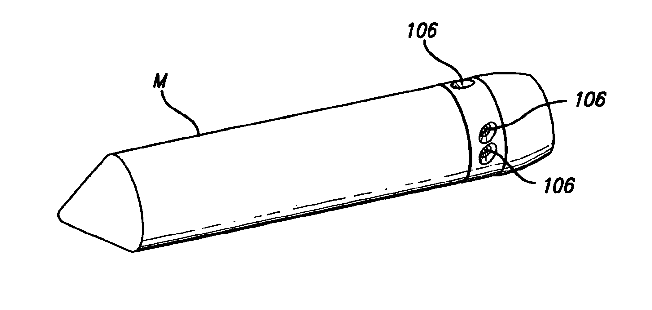
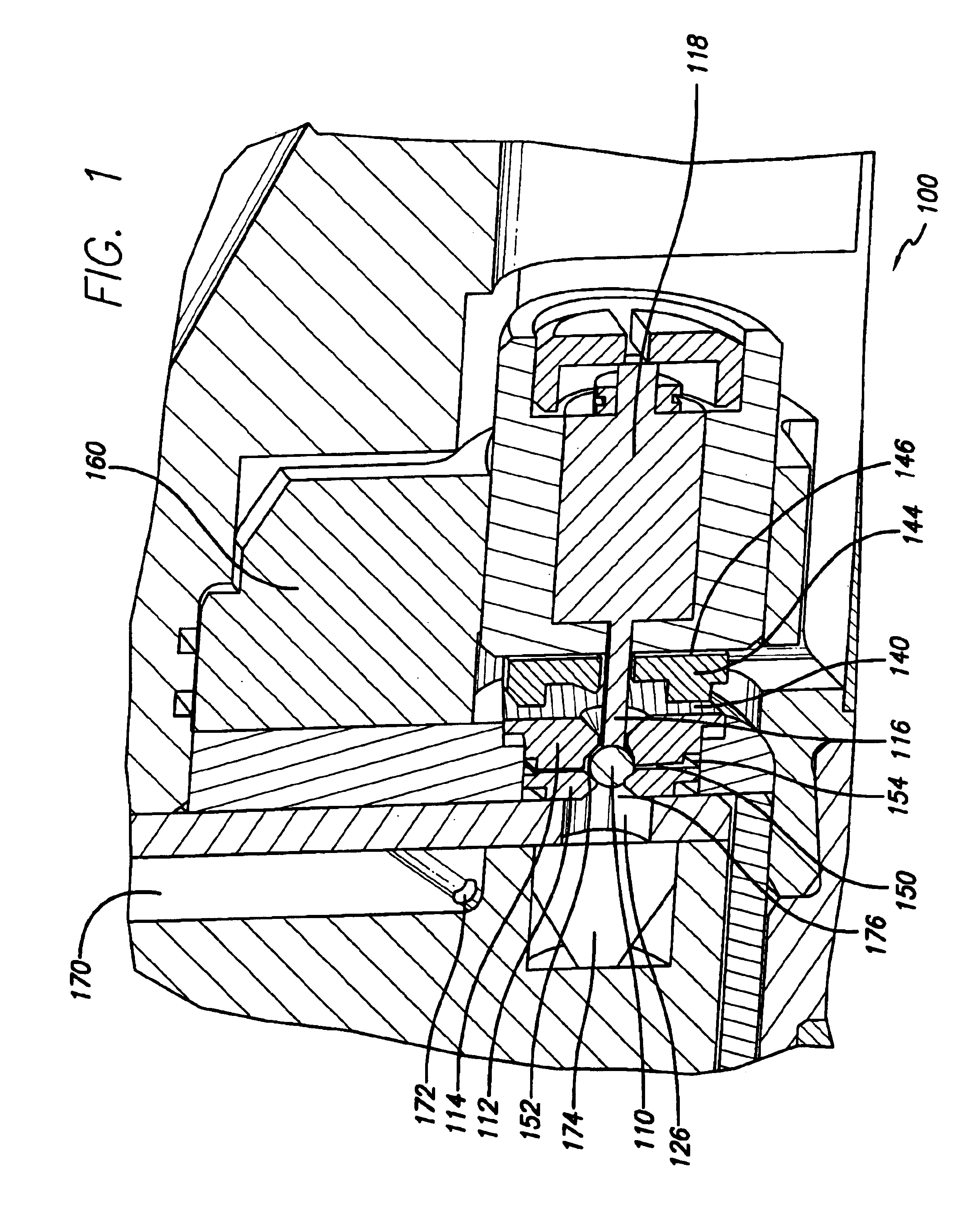
[0033]The invention is embodied in a pilot valve 100. By providing a pilot valve system that can withstand the operating conditions of generally-adjacent missile thrust from solid propellant, the pilot valve 100 provides a significantly more useful pilot valve and control system for thrust nozzles, especially thrust nozzles exerting la...
PUM
 Abstract
Description
Claims
Application Information