Cylinder head gasket

a cylinder head and gasket technology, applied in the direction of engine sealing, machine/engine, engine sealing arrangement, etc., can solve the problems of gaskets being subjected to constant changing compression forces, cylinder head and cylinder block warping under, and oscillation of the gap between the cylinder head and the cylinder block

Inactive Publication Date: 2005-10-04
DANA AUTOMOTIVE SYST GRP LLC
View PDF24 Cites 27 Cited by
  • Summary
  • Abstract
  • Description
  • Claims
  • Application Information

AI Technical Summary

Benefits of technology

[0004]The present invention is directed to a gasket that produces substantially equal sealing stresses about cylinder apertures using at least a stopper layer having a generally uniform thickness and a variable thickness spacer layer.
[0005]Specifically, the invention is directed to a gasket comprising at least one stopper layer that employs a stopper and a sealing bead. Joined to the stopper layer is at least one spacer layer. The spacer layer has both a first thickness and a second thickness. The second thickness of the spacer layer is generally less than the first thickness to evenly distribute the sealing stress about the cylinder apertures.

Problems solved by technology

A typical problem associated with these multi-layered steel gaskets is that, when assembled, a cylinder head and cylinder block tend to warp under the forces of the screws joining the head and block together.
Another challenge that is experienced in the field of cylinder head gaskets is that the gap to be sealed between the cylinder head and the cylinder block oscillates because of fast pressure and temperature changes in the engine.
Therefore, the gasket is subjected to constantly changing compression forces, particularly in the area of the combustion chamber holes.
The changing compression forces reduce the durability of the sealing beads and stoppers arranged around the holes because unequal sealing stresses result.
The unequal sealing stresses also produce a poor quality seal between the cylinder head and cylinder block thereby permitting leaks and contamination of cylinder openings.

Method used


Image

  • Cylinder head gasket
  • Cylinder head gasket
  • Cylinder head gasket

Examples


Embodiment Construction

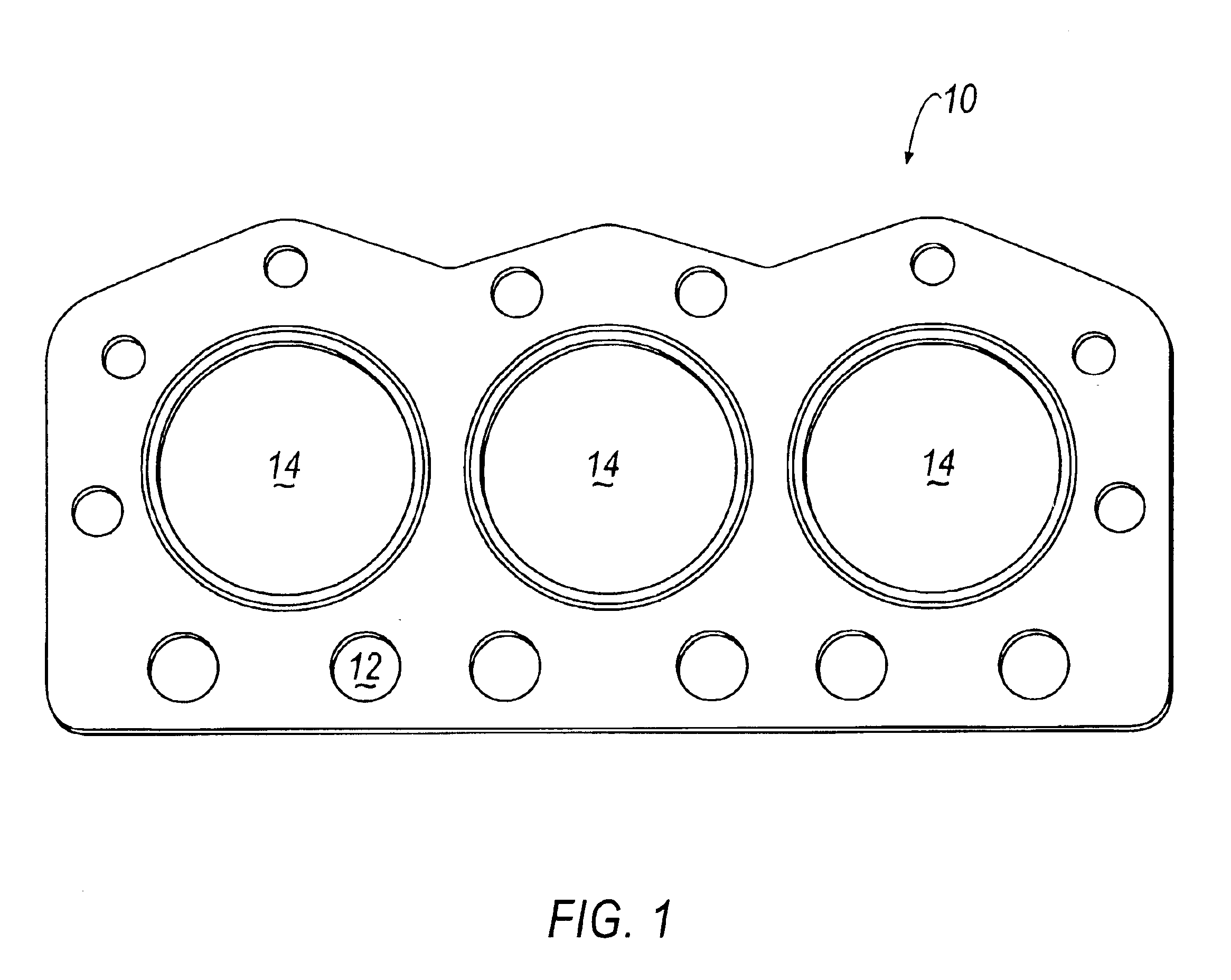
[0021]As seen in FIG. 1, a gasket of the present invention is generally referred to at 10. The gasket 10 includes a plurality of apertures such as bolt holes 12 and combustion openings 14 that mate with corresponding apertures of a cylinder head (not shown) and cylinder block (not shown). When fully assembled, the gasket 10 is positioned between the cylinder head and cylinder block to fill gaps and seal around various holes 12 and openings 14. The seal generated by gasket 10 serves to prevent leaks and contamination.

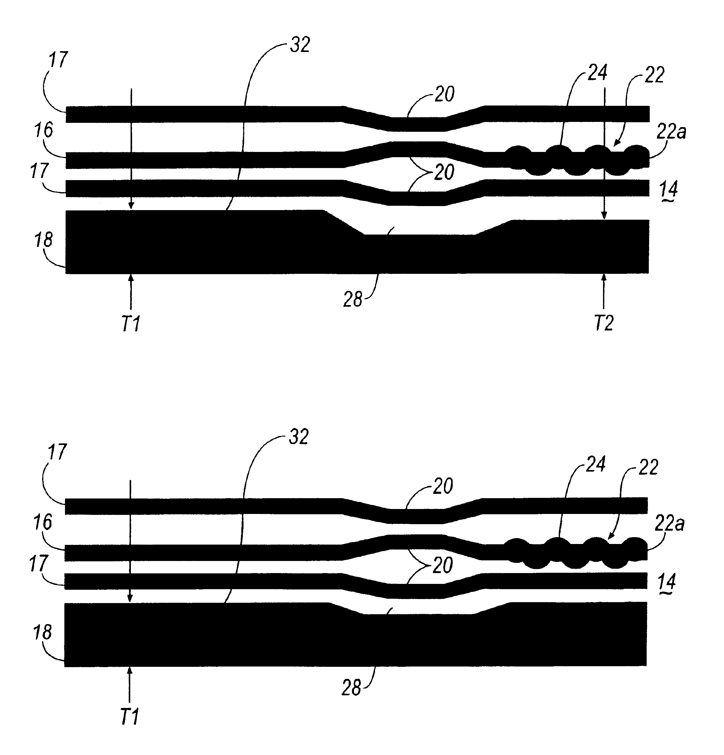
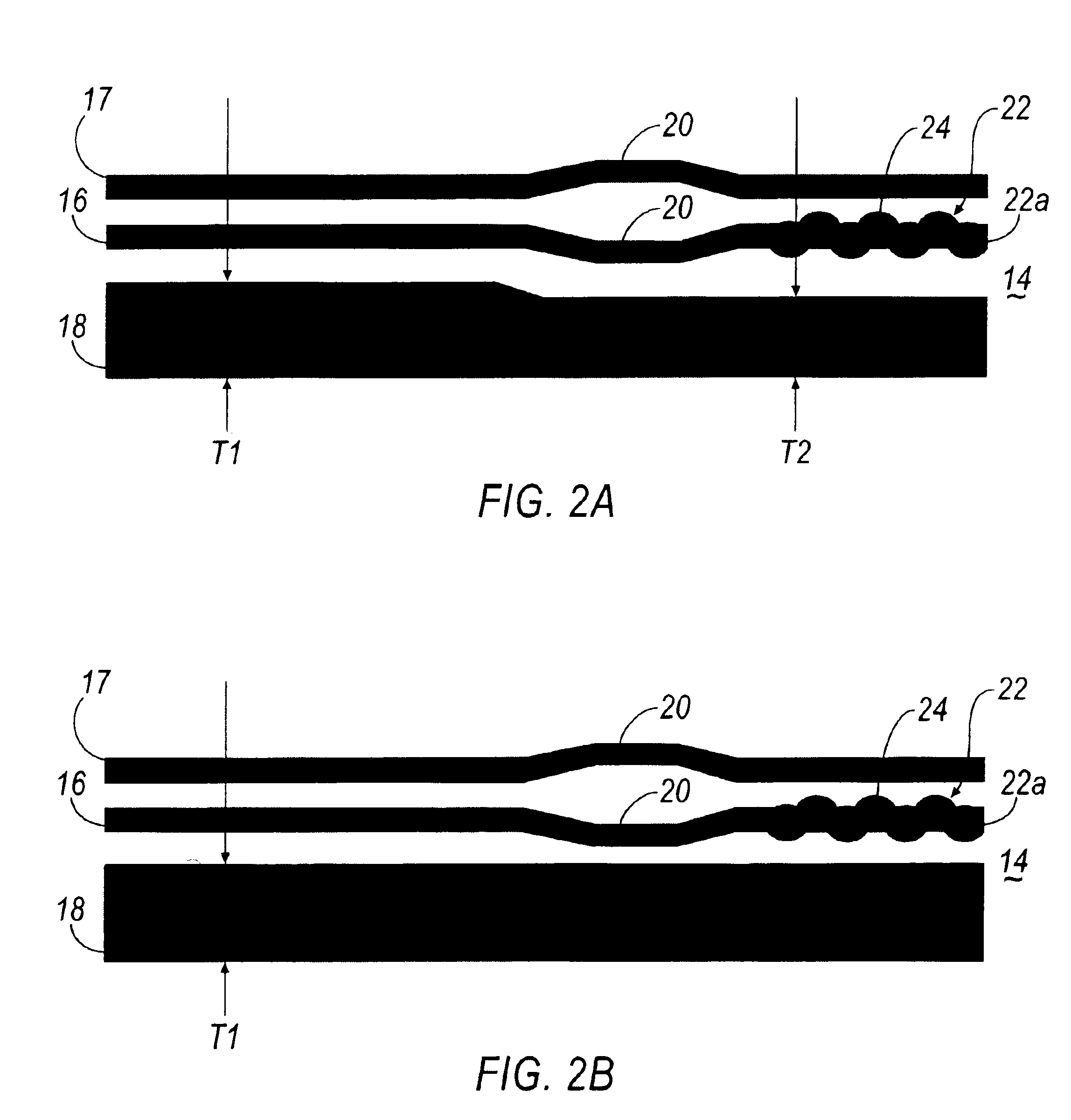
[0022]However, warpage of the cylinder head and cylinder block are created when a fastener (not shown) is tightened to mate the cylinder head and cylinder block. As described above, these warpage's result in unequal sealing stresses around the bolt holes 12 and combustion openings 14. Furthermore, rapid temperature and pressure changes within the engine cause the cylinder head and block to oscillate, thereby further varying sealing stress between the head and the block. ...


PUM


Abstract

A multi-layered cylinder head gasket for positioning between a cylinder head and a cylinder block of an engine includes a spacer layer and a stopper layer. The stopper layer includes either a wave or rigid stopper positioned at a periphery of an aperture of the stopper layer. A sealing bead is positioned adjacent the stopper. Overall, the stopper layer has a generally uniform thickness. The spacer layer, however, has first and second thicknesses with the second thickness being generally less than the first thickness. The second thickness of the spacer layer mates with the stopper and sealing bead when the stopper layer and spacer layer are joined together. A transition area is positioned between the first and second thicknesses. The variable thickness of the spacer layer permits the gasket to provide generally equal sealing stresses while subjected to variable compression forces.

Description

TECHNICAL FIELD[0001]The present invention relates to a multi-layered cylinder head gasket and in particular to a gasket having a stopper layer of generally uniform thickness that cooperates with a spacer layer of various thickness.BACKGROUND OF THE INVENTION[0002]In the field of multi-layer steel cylinder head gaskets, the gaskets are generally formed of a plurality of sheet metal plates. A typical problem associated with these multi-layered steel gaskets is that, when assembled, a cylinder head and cylinder block tend to warp under the forces of the screws joining the head and block together. Accordingly, the sealing stress between the cylinder head and cylinder block must be greater surrounding the combustion chamber opening than in the area surrounding the cylinder head screws. Gaskets often contain sealing beads and stoppers in the edges of the sheet metal plates of the gasket around the combustion chamber holes, to focus the sealing stress on the combustion seal and provide el...

Claims


Application Information

Patent Timeline
Patent Type & Authority Patents(United States)
IPC IPC(8): F02F11/00F16J15/08
CPCF02F11/002F16J15/0825F16J2015/085
Inventor KESTLY, MICHAEL J.
Owner DANA AUTOMOTIVE SYST GRP LLC
Why Eureka
Try Eureka