Reciprocating head press

a head press and recoil technology, applied in the field of recoil presses, can solve the problems of affecting the appearance of the equipment, affecting the speed of the press, and other problems relating to timing, and achieve the effect of reducing the cost of equipmen

Active Publication Date: 2005-10-04
AM MFG
View PDF8 Cites 13 Cited by
  • Summary
  • Abstract
  • Description
  • Claims
  • Application Information

AI Technical Summary

Benefits of technology

[0009]The present invention provides an apparatus and method for flattening dough pieces which combines the advantages of pressing the dough to obtain circular or other desired shapes, allows for heating the dough while pressing, allows for continuous operation, and particularly of the belt carrying the dough pieces, and avoids the problems associated with various approaches known in the art.

Problems solved by technology

While such an operation greatly increases the speed at which the dough pieces can be flattened into disks, such as tortillas and pizza crusts, the intermittent movement of the belt places a restriction on the speed at which the overall operation can be carried out, and the starting and stopping of the belt causes other difficulties relating to timing, energy requirements, wear and tear on the equipment as well as movement of the dough pieces relative to the belt.
While this arrangement allows for continuous movement of the belt, and so avoids the problems associated with intermittent operation of the belt, this approach creates its own problems, for example, the resulting dough pieces typically are not circular, but rather are oblong in shape, which are not as aesthetically pleasing for tortillas and pizzas.
A raised rim, such as is used in pizza crusts, cannot be formed with this method and the dough itself responds differently when it is rolled out, as opposed to being pressed, which can affect the subsequent cooking of the dough.

Method used


Image

  • Reciprocating head press
  • Reciprocating head press
  • Reciprocating head press

Examples


Embodiment Construction

A. Overview

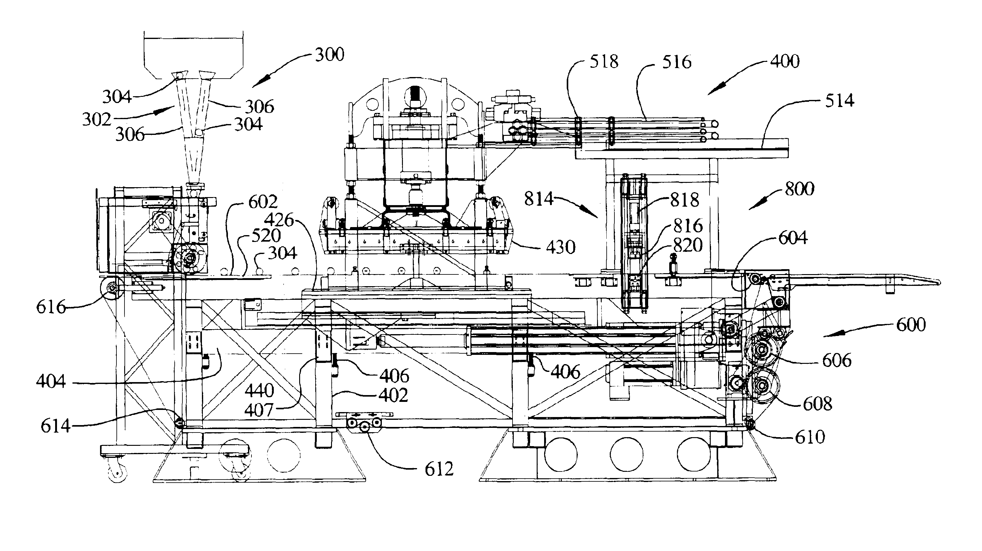
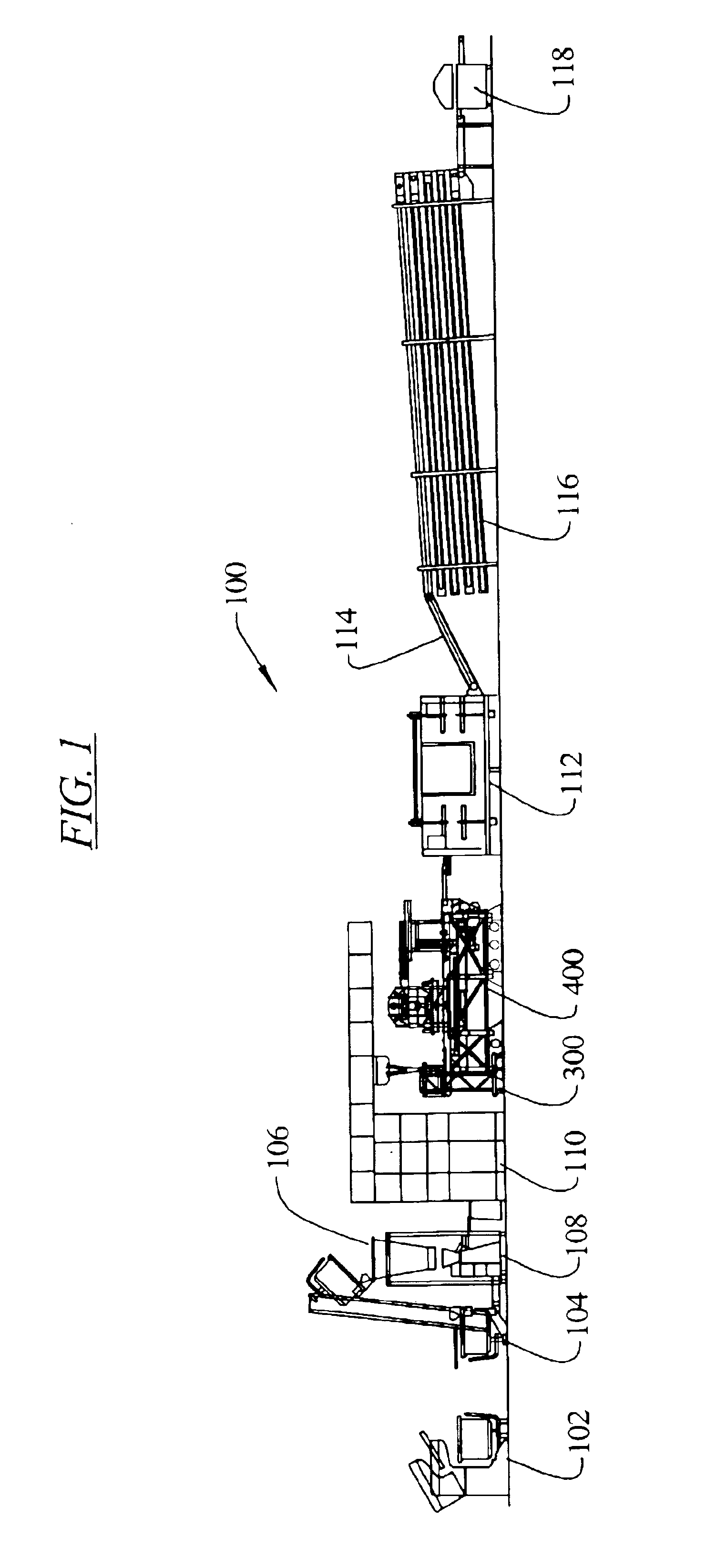
[0051]The present invention relates to a press 400 for flattening dough pieces, for example, flattening dough balls into pancake like shapes for tortillas, pizza crusts and similar food products. Because of the high rates of product through the press, the press is typically arranged in a system 100 of mechanisms as illustrated schematically in FIG. 1. This system can begin with a dough mixer 102 in which flour, corn meal or similar product is mixed with water and other ingredients according to some particular recipe to produce a large batch of dough. The mixer may include an elevator 104 to raise a portion of the mixer to an elevated position where the mixed dough batch is dropped into a holding hopper and dough chunker 106. In the holding hopper and dough chunker 106 the batch of dough is held and then chunks of dough are dispensed into a dough divider and rounder 108 in which the dough is divided into much smaller portions and is rounded into ball shapes. The rounder 10...


PUM

PropertyMeasurementUnit
lengthaaaaaaaaaa
speedaaaaaaaaaa
circumferenceaaaaaaaaaa

Abstract

A press for flattening dough pieces is provided having a floor supported frame, an endless conveyor belt movably carried on the frame and presenting an upper horizontal surface, and at least one movable platen carried on the frame for pressing the dough pieces against the belt. In an embodiment, a sub frame is adjustably supported by the frame to permit leveling and adjustment of said sub frame relative to the frame. Attachment mechanisms are provided for securing the sub frame to the main frame following adjustment between the two. In an embodiment, at least two movable platens are carried on at least one of said frames, both of the platens being movable in a longitudinal horizontal direction and at least one of the platens is movable in a vertical direction. A linear actuator is drivingly connected to the two movable platens. In an embodiment, a loading system for loading dough balls onto the belt is provided. The loading system includes a transport mechanism to receive dough balls in a sequential stream and to deliver the dough balls to the belt at a speed equal to a speed of the belt. In an embodiment, a belt splicing hot press is carried on the frame operatively engageable with the belt to splice together severed ends of the belt to form a continuous endless belt.

Description

[0001]This application claims priority to U.S. provisional patent application Ser. No. 60 / 400,169, filed on Aug. 1, 2002.BACKGROUND OF THE INVENTION[0002]The present invention relates to presses used to flatten dough-like material, for example edible dough materials used in tortillas, pizzas and similar food items.[0003]Presses for dough material are well known and one type comprises a stationary press in which individual dough pieces are placed under a vertically movable platen, the platen compresses and spreads out the dough and then the platen is moved away revealing a flattened dough piece which must be manually removed. Another type is an automated dough press which typically comprises a moving belt and a vertically reciprocating platen. Generally the belt is stopped, and while stopped the platen, moves downwardly to engage and flatten a dough piece against the belt and then the platen moves upwardly. Subsequently the belt indexes to the next position to present a new series of...

Claims


Application Information

Patent Timeline
Patent Type & Authority Patents(United States)
IPC IPC(8): A21C11/00
CPCA21C11/006
Inventor SCHULTZ, JAMES L.
Owner AM MFG
Why Eureka
Try Eureka